I got all of the firmware straightened out and this works pretty well now. This particular software build only handles DCC addresses 0-99 but I’ll be fixing that on the next firmware upgrade.

You only need this one board and it will enable the Protothrottle to control all of your Airwire Locomotives. It still needs another pass on the PCB and an enclosure but I’m pretty happy with the innards. I’m going to build up a few and see if anyone wants to do some beta testing for me.

UPDATE 3/11/19- Now in Beta, I have the full 4 digit addressing working.

I thought I would post an update on my system progress. Above is a shot of the Protothrottle and the node configuration screen. I’ve got this almost finished, I only need to add some refinements for the servos in order to do live steam or in the case of diesel DCC locomotives, control the front and back couplers.

Anyhow, to recap some of what I said in previous posts- the configuration web app runs on a Raspberry Pi Zero W which is configured as a stand alone Linux server. I did this so it will work on any display device using a browser- phones, tablets and computers, regardless of brand (IoS, Android, Windows, Mac). The hardware is very similar to the ISE ESU hardware, in fact, it’s almost identical. (a pic is in one of the posts below)

The Zero is configured as a Wifi access point with DCHP and DNS. Backend services are provided using Flask (python) with an html and javascript front end. I’ve added MySql and Redis to keep track of things and there is a background process that runs all the time to handle the root access to the Xbee board. It sounds complicated and the software was a bit of a challenge but once its configured properly, it just works.

I’ve tried to keep this very simple, above is the main page when you connect to the RpiZero web server. You can click or touch the ‘scan’ button and all of the Xbee devices on the network will be queried and saved. You can then click any of the nodes to ‘zoom in’. Each node will support a DCC output and servo outputs. I run both diesels and live steam so I am building in servo control for both. ‘Diesel mode’ will be used to control the two couplers on a battery DCC locomotive. ‘Steam mode’ will allow the throttle and direction controls on the PT to move servos in a live steam locomotive.

Here is a shot of the main node configuration. There will be another screen when I get my ‘Airwire Translator’ working but that’s a whole other project. I do have the basics for that coded up and prototyped but it will be a while before I get that one together.

Anyhow, a few specifics on the parameters- the Protothrottle ID and the base ID are pretty much fixed unless you want to run multiple combinations of protothrottles- the Xbee DCC Node looks at both of these values and they have to match or the message is ignored.

The loco address is (obviously) the address of the locomotive you wish to control. Unlike normal DCC implementations, I don’t change the DCC address on the decoder- it’s always set to the default- 3. Since the Xbee Node only talks to one DCC decoder (internal to the locomotive), it just makes things more complicated if you change it so I require it to be fixed. The Xbee addressing and messages take the place of the DCC ‘network’ (ie, the ‘track’)

Below the Loco Address is the consisting setup. You can set consisting to OFF, FWD or REV and then enter the address of the lead locomotive. If anything other than ‘OFF’ is set here, the Xbee node will respond to the consist address and ignore it’s own address. Since the Xbee message is broadcast to all locomotives at the same time, this gives you unlimited consisting.

Below the Consist setup is the CV Programming parameters. Enter any CV Address and data into these windows and press ‘Prg’ to send a CV programming command to the locomotive. At some point I will expand this to include english language setups for both the Soundtraxx TSU-4400 and the TCS Wow 501, but for now this gets the job done.

Next is the servo setup. There are two servo modes, ‘Couplers’ and ‘Steam’. Couplers (servos) can be assigned to the DCC function codes to open and close them. This is not completely implemented yet, but the hooks are there. In ‘Steam’ mode, the Protothrottle throttle lever will be passed to servo 0 (taking into account the low and high limits) so that you can control the speed of a Live Steam Locomotive. The second servo will then be used for direction control. For both of the servos, regardless of the mode, you can set a reverse and a high and low limit.

So, that’s about it. I will be installing all of this in a couple of my locomotives to do some ‘real world testing’ once the weather improves a bit and spring rolls around.

I have two of these for the time being (one is a loaner from iowa scaled), so I am putting some cycles into developing a web app to handle the Xbee network these guys inhabit. It is way cool how the Protothrottle backend works. It sends out broadcast packets to every Xbee on the network but leaves a huge space for directed messages.

In light of that, I’ve come up with this minimalistic setup to send those directed messages. Super simple hardware. A Raspberry PiZero W, configured as a Wifi Access point with an Xbee as a USB device. It’s running Apache web server and Python Flask on the backend. I’ve thrown in MySQL and reddis (database apps) and created the basics for a web app. Because of the way linux works, I need a background process that runs as root that actually talks to the USB/Xbee. (the web app doesn’t have access to the hardware) I run two reddis queues so the web code can build the messages and then the root process can receive and send them. Took a while to get that working right but it’s doing quite well now. Everything starts at powerup. I like stuff to ‘just work’ when you turn it on.

Using this interface, I can scan for all the nodes on the xbee network and then direct specific message packets to each using a web based interface. Or in other words, I will be able to configure a DCC decoder in a locomotive with my smart phone while I control it with the Protothrottle. Way cool!

Above is how the Windows PC sees the RPiZeroW, it’s just another Wifi network. Once you join here, the RPiZW (linux) handles all of the DHCP and DNS stuff so you can use any browser to get to it. Below is the console login using windows 10 bash. You can just ssh into the Rpi, just like a big ole honkin web server box (even though its only as big as two postage stamps, ha) As you can see, all of this is over Wifi, I have no hardwired ethernet.


Doing a little running outside today, it was a nice day. My layout is a bit thin, needs some ballast and maintenance, it’s been a tough weather season this year, I have not kept up.


So here are the insides. I like that it’s all self contained, no track power- 3000mah LiPo prime mover, the 5A power amplifier with the big heatsink drives the TCSWow. (You can’t see it here, its underneath the Xbee Receiver)

My receiver board has a standard Xbee sort of foot print for the network chip, it’s what I originally designed it for. Lately I have had a Bluetooth compatible radio chip in it so I could drive my trains with my Android Phone. I swapped that out with an Xbee Series 1 so it would get the Protothrottle network traffic. I coded up some new firmware for the receiver and flashed it into my USAT PRR GP9. Worked really well. I think I have most of the bugs worked out, just needs a bit of tweaking.

I changed the brake on the protothrottle to ‘pulsed’ on F7 for the TCSWow and it works great. I love that brake squeal. I still have lots to do here, the decoder is still ‘out of the box’ I have not tweaked it much at all. I want to configure it with my smart phone, I don’t like the ‘audio assist’ thing much- I have some of that code built out but it will take a while to get it going.

Thanks to Craig Townsend and Iowa Scaled Engineering, I now have one of these to play with for a bit. First look and it’s doing Xbee pretty much like I thought- I’m already seeing traffic from it. I’ll be integrating this into my own receivers plus working on a translator to drive Airwire devices. However, tomorrow (1/1/2019) is my last day of break so it will take me a bit to get everything refactored. I have the basic framework up and running on my development boards but now I have to interface the Protothrottle packets into my message handlers. Should be fun!


Santa brought me a bunch of circuit boards and other electronic goodies, so I decided to try some quick porting of existing code and protocols. I really like the knob on the Airwire Handheld but I much prefer changing the parameters of the DCC decoder with my phone. So for fun I refactored some code from my bluetooth receiver, added a CC1101 radio modem and now my phone can talk Airwire. Way more fun! So now I get the best of both- the big knob on the Airwire throttle and the nice color UI on the phone to change the DCC parameters. (Notice the big knob on the Airwire Throttle- I had a really nice Aluminum antique knob from another project so I mounted it instead of the plastic one that comes with it. Much better feel.)


The phone will do it all now, I can also drive the train with the phone if I wish (probably not) plus I can setup all the other DCC parameters like the engine choice, the acceleration/decel, brakes, etc. All with plain text and pretty colors. Can’t beat that. I do have to add some parameter entries to the phone like the Airwire Channel number and the DCC address, but I’ll get to that soon.


Above is the bluetooth/airwire transmitter side. For the most part, this is a complete design. The PC Boards require just a couple of tweaks but they are in good shape. I’m using the Bluetooth chip to intercept commands from the phone and then translating those into a logic level DCC stream. That feeds directly into the CC1101 radio modem which then talks to the Airwire receiver.

This is the receiver side. At the moment it’s just adhoc on the breadboard but I’m also working on a couple of smaller receivers. The DCC amp at the end combines the Battery voltage (or in this case, wall wart for testing) and changes the logic level signal into ‘real’ DCC. This drives an Economi (Soundtraxx) 2amp Decoder. The soundtraxx is just for testing, this will eventually be going into a GP38 with a TCSWOW 5 Amp decoder and 3300mah Lipo.

Anyhow, below are two of the receivers, one is the ‘deluxe’ version which contains a complete Arduino ProMini board, and the ‘minimal’ which is an Attiny24 design. These also are complete boards. The Promini design can be altered with Arduino Studio, the smaller one is not programmable, you use the jumpers to set the Airwire Channel.

Here are a few images of the logic analyzer and what’s going on between the devices. The top four traces are the SPI line to and from the modem on teh transmitter side. The bottom two lines are the transmit side DCC signal and the receiver side- they line up perfectly. Just blasting DCC over the air is a pretty brute force way to do things but it does work quite well and is fairly east to duplicate.

I got bored with Bluetooth and decided it just wasn’t going to give me what I wanted in terms of a control network. So I figured I would go back to one of my favorite wireless control devices, Xbee. I love those little blue boards. Since Xbee offers the Digimesh option for it’s devices I upgraded all my modules to the latest firmware and started designing some stuff.


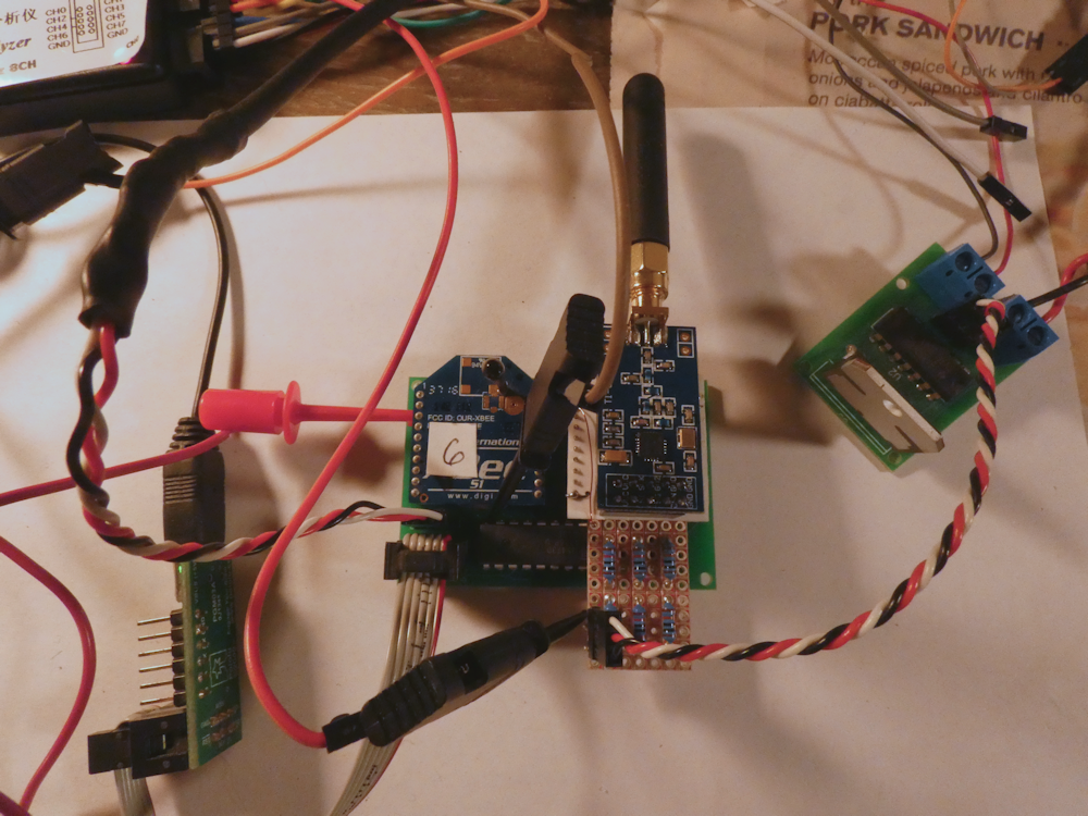
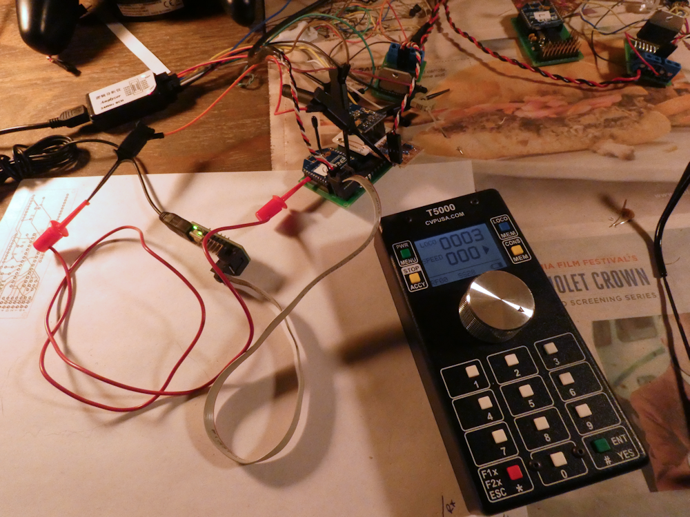
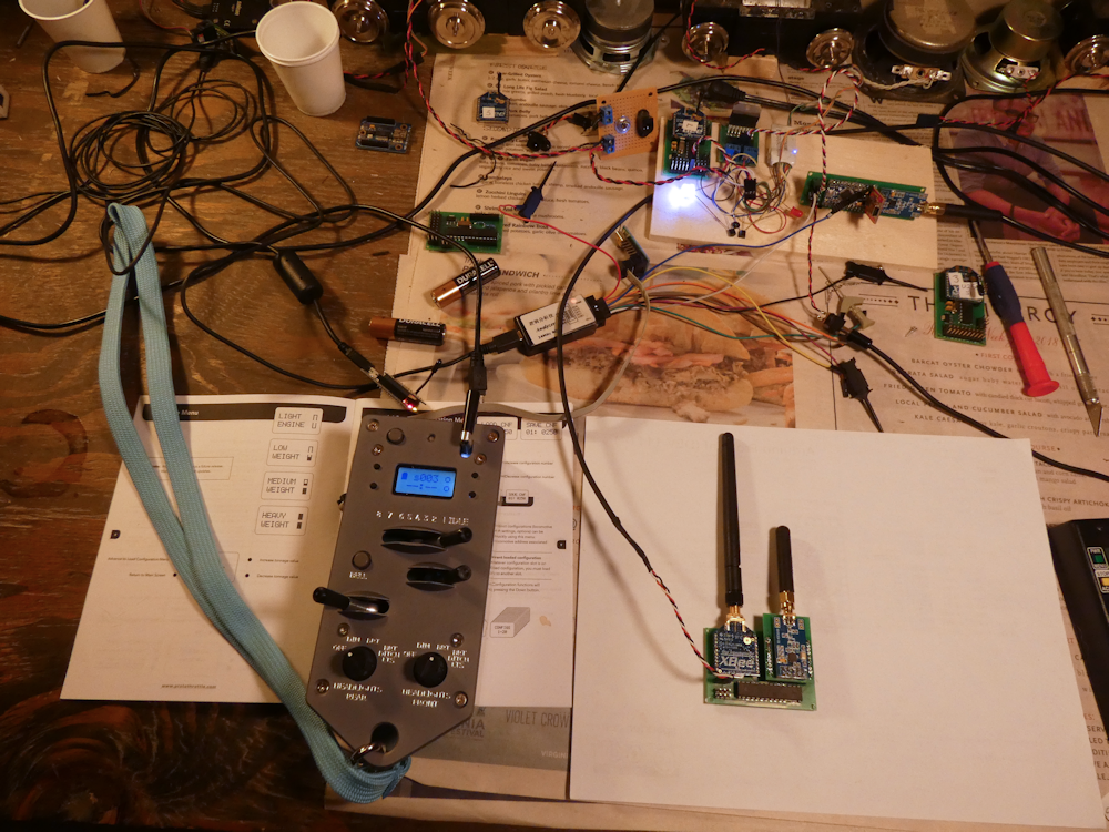
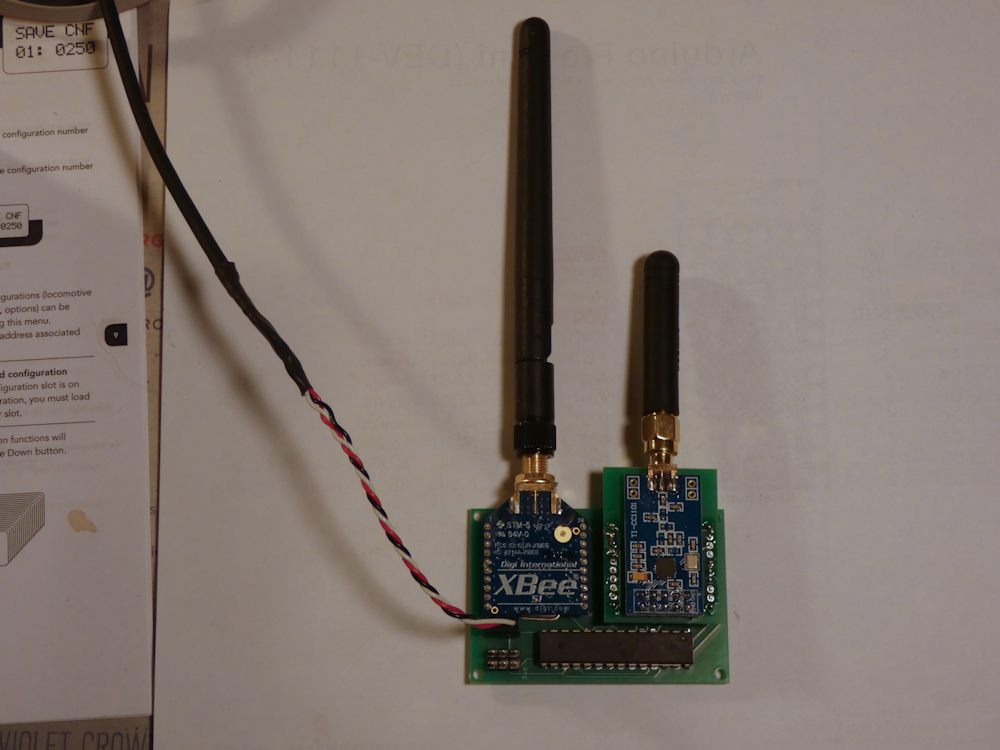
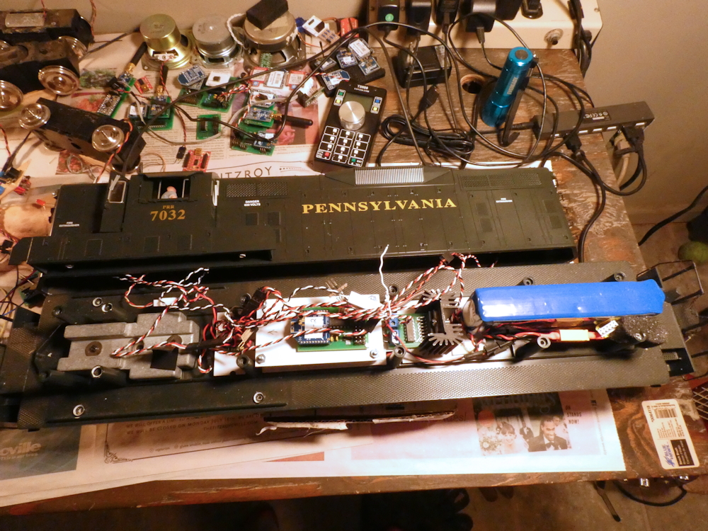
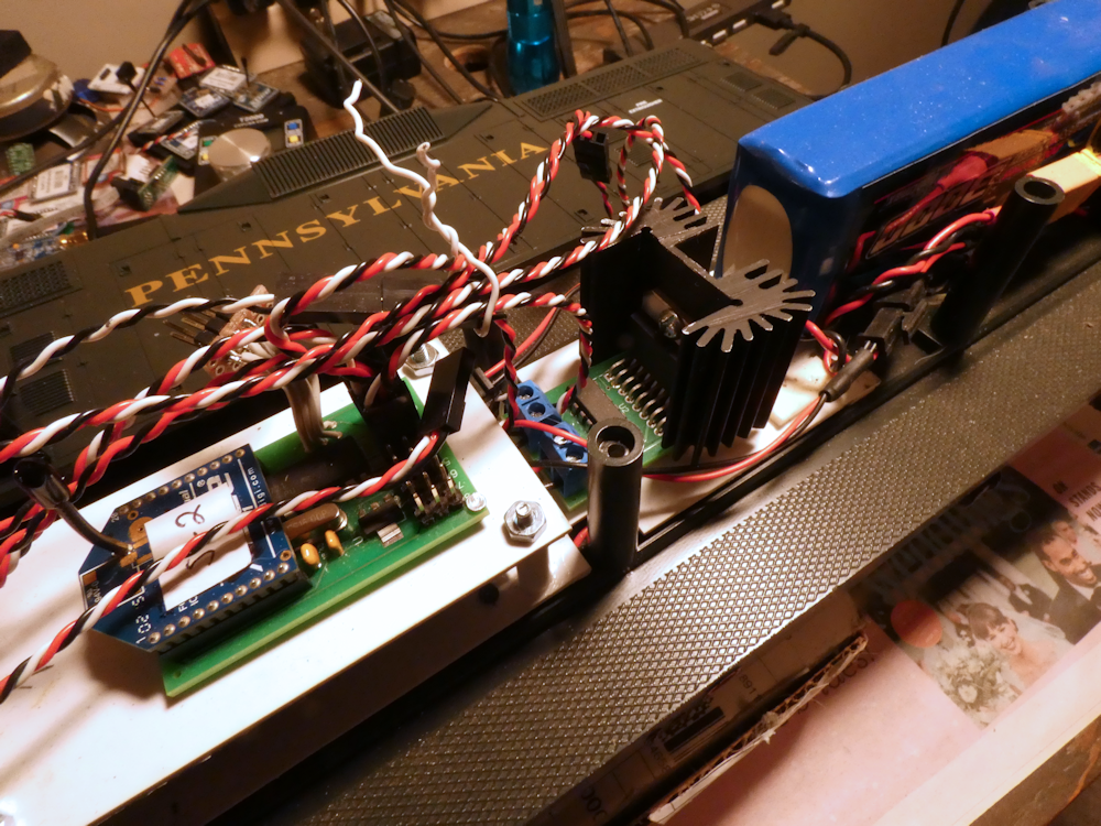
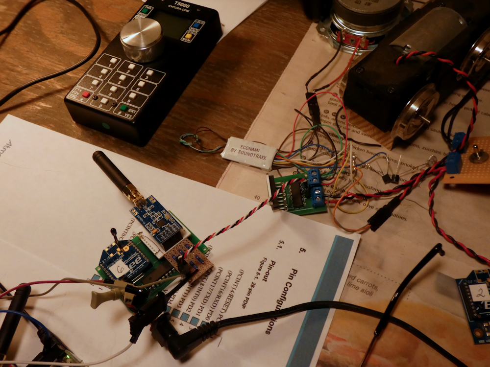
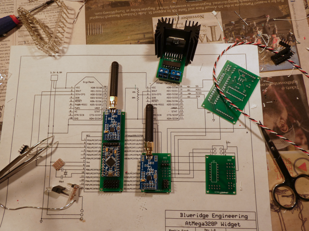
Above is the basic Airwire to Xbee breadboard. The ‘translator’ is a PCB that contains an Xbee in one socket and a CC1101 radio modem module in the other. The Airwire modem is mounted to an ‘Xbee blank’ that I cut out on my Probotix Router, this will be a PCB at some point. All of this is controlled by my favorite microcontroller, the Atmega328, the same chip in the Ardunio Pro Mini. I clocked it at 16Mhz and implemented a priority scheduled bare bones RTOS to handle the various control tasks.

What I am doing is intercepting the DCC data streaming from the Airwire Throttle (many thanks to Eric Reuter for his radio init data) and breaking out the DCC messages into individual packets. This lets me filter out the constant barrage of redundant messages and encapsulate them into Xbee message payloads. Only when the data changes is an Xbee packet sent out.

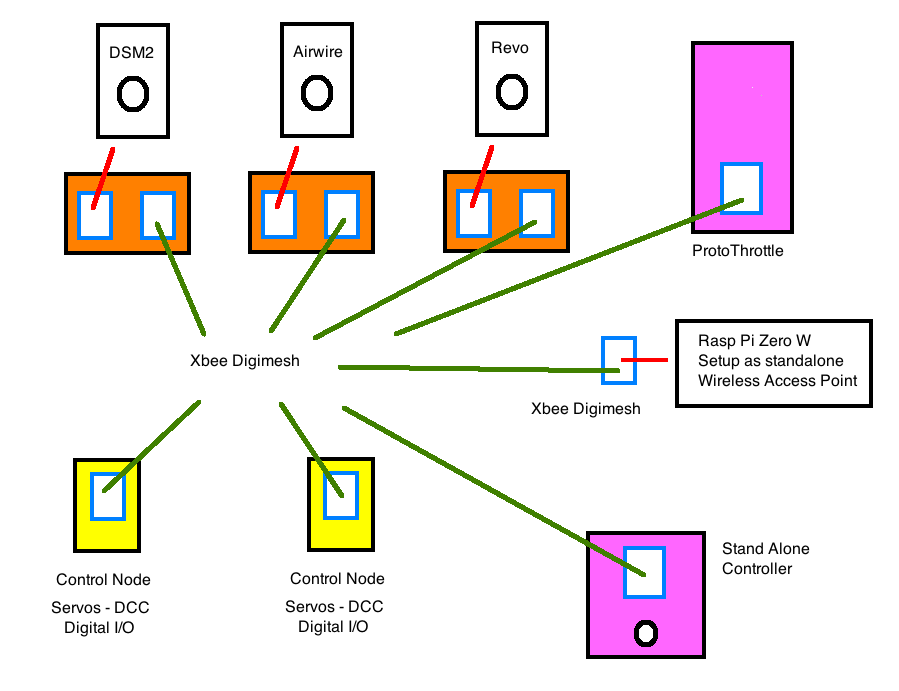
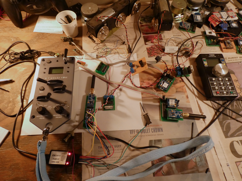
This is the basic network layout. ‘Translators’ intercept the various control packets from handheld controllers, translate those control messages into a standard list of Xbee payloads and ship them off to the destination. Since there really isn’t a ‘master’ or ‘slave’ on a mesh network, these messages can also go to multiple recipients. There are all sorts of possibilities here using a single standard wireless message transport system like Digimesh.


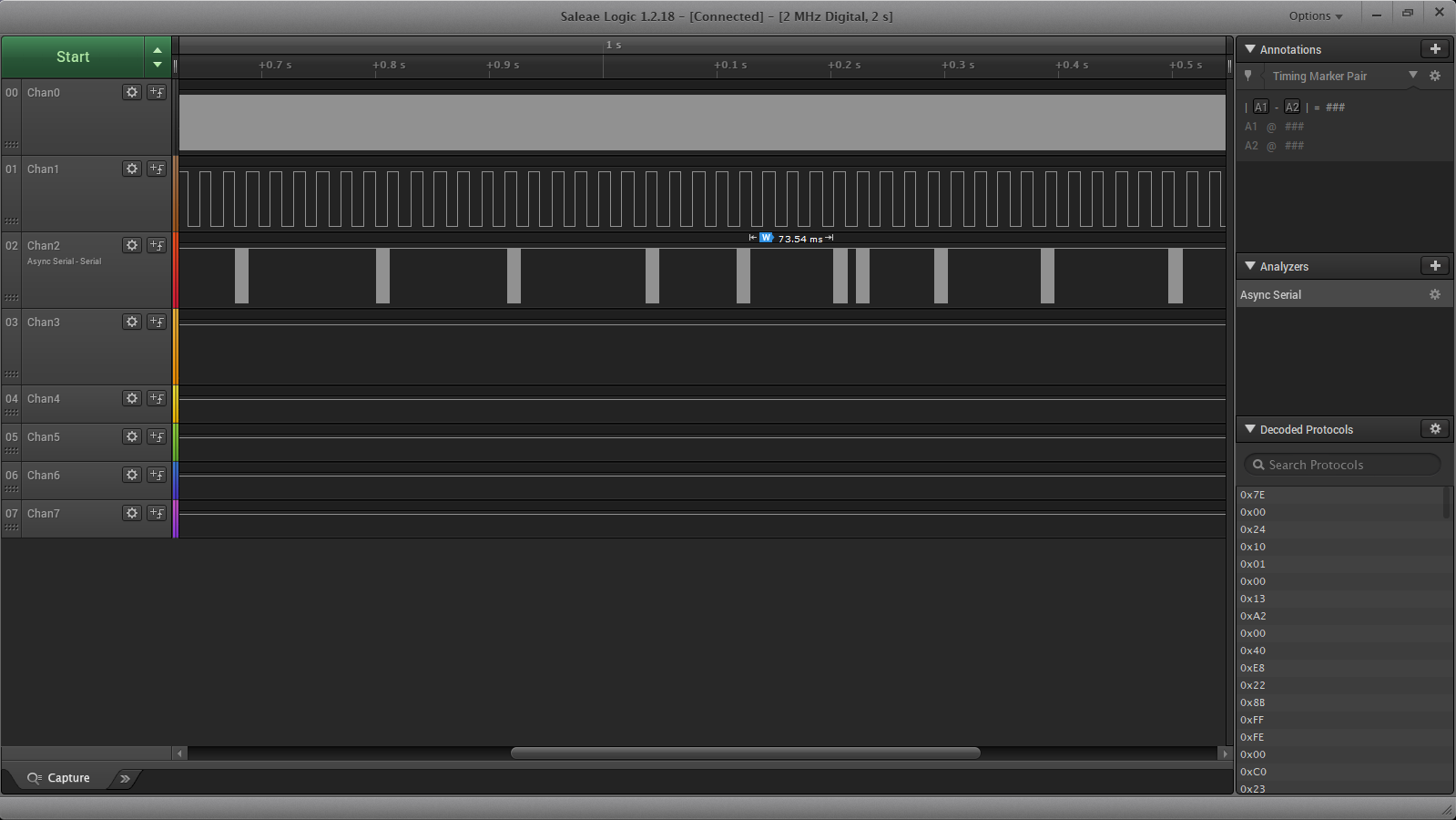
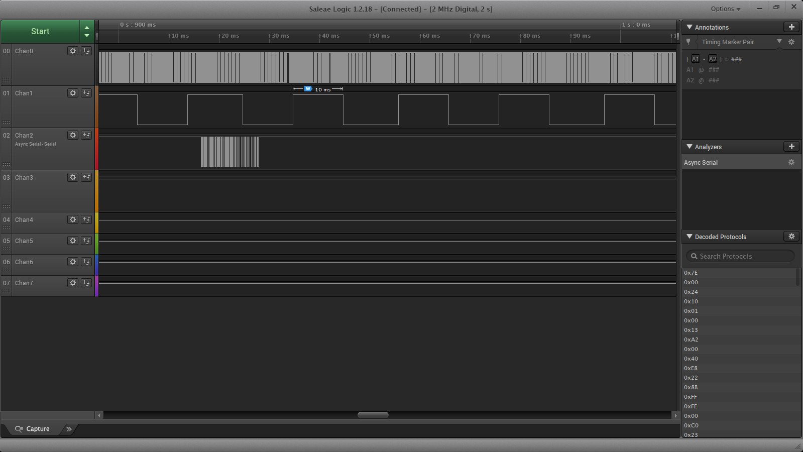
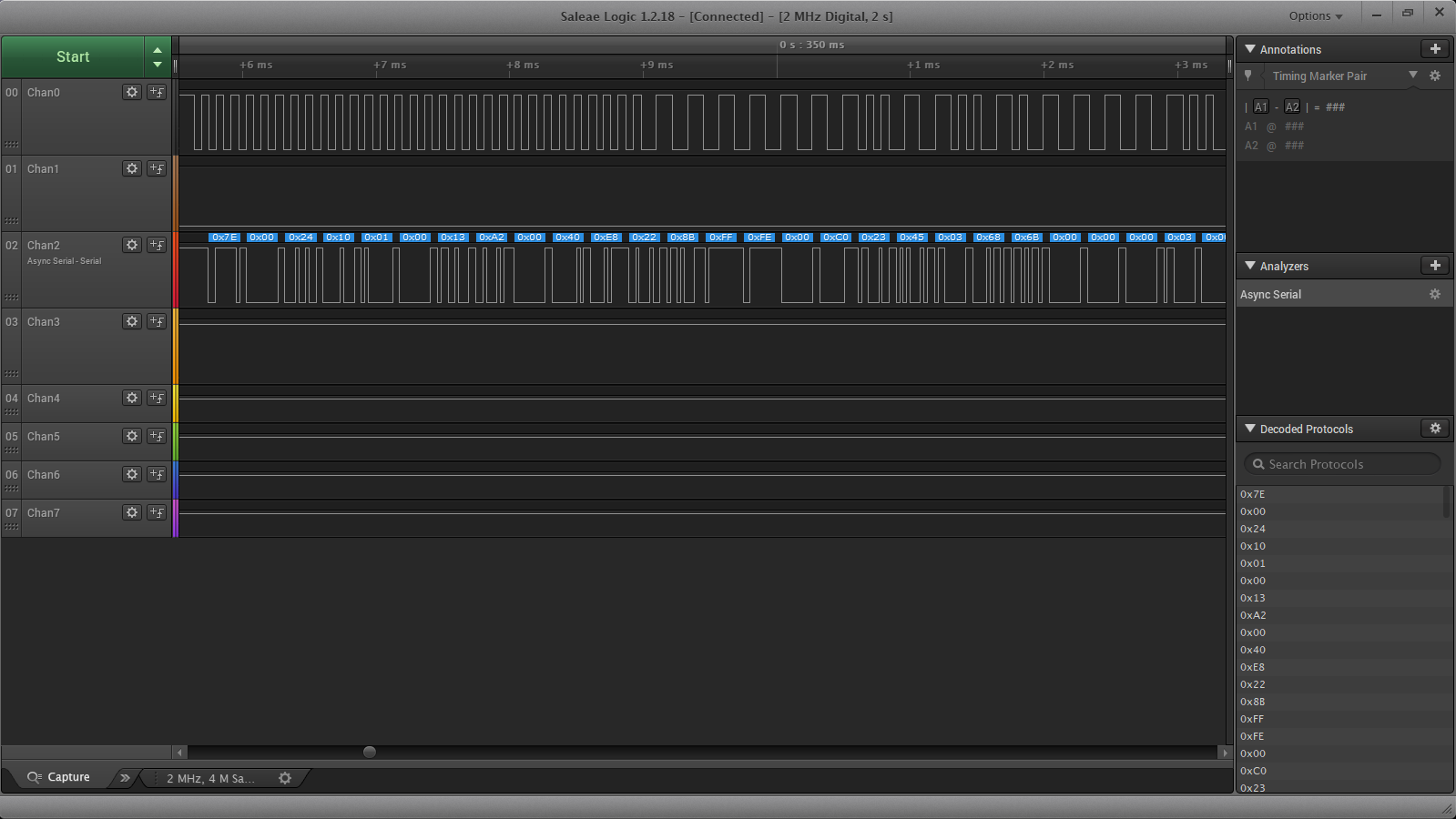
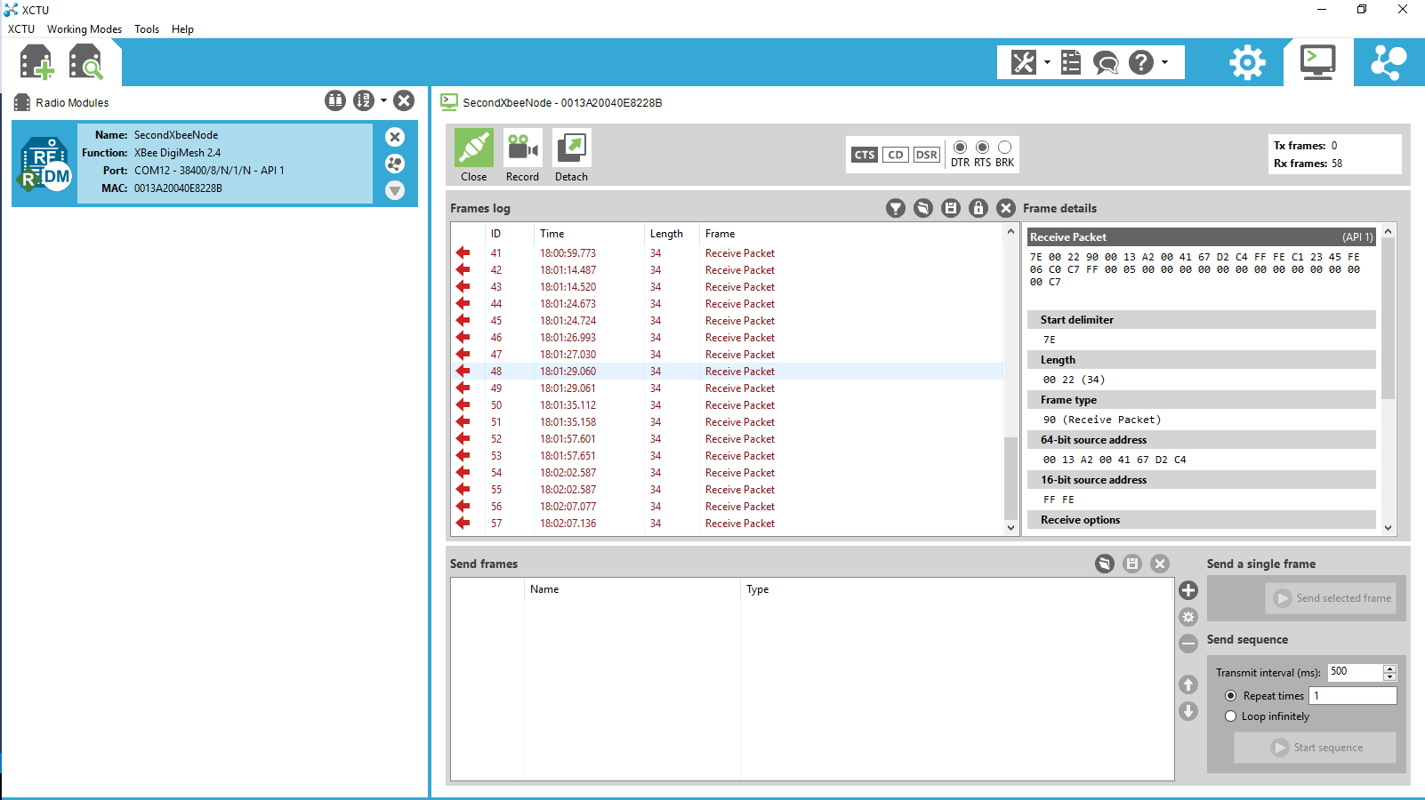
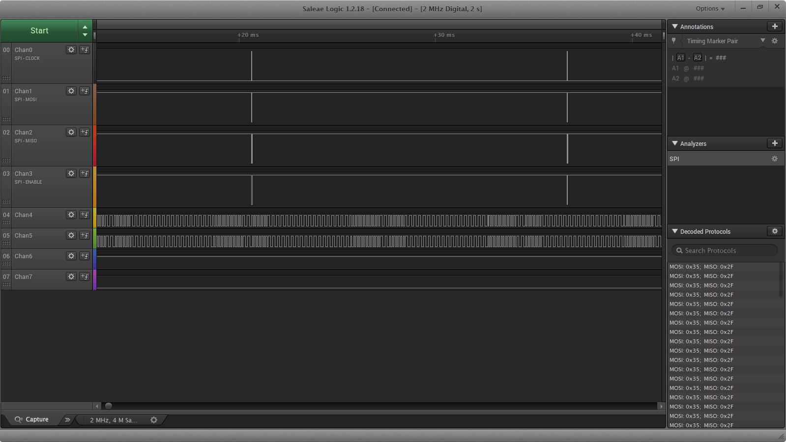
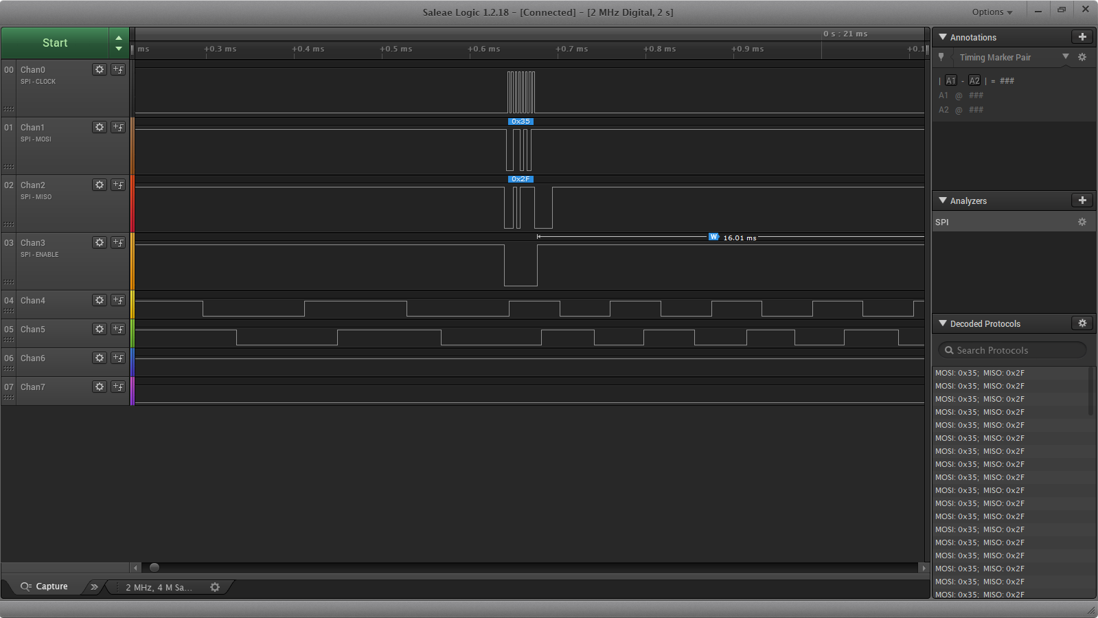
Above are the pertinent observations – logic trace and reception of the Xbee packet on the PC via XCTU. Top trace is the DCC from the Airwire Throttle, second is one of the RT clocks, the 10ms one, the bottom is the async data frame to the xbee. There is still much work to be done but the basics are now in place. I can convert all of my various control methods, Airwire, DCM2, Bluetooth, etc into a single, point to multipoint Industrial IoT mesh network. Xbee digimesh is very well document and pretty much an industry standard.

Xbee Digimesh Documentation


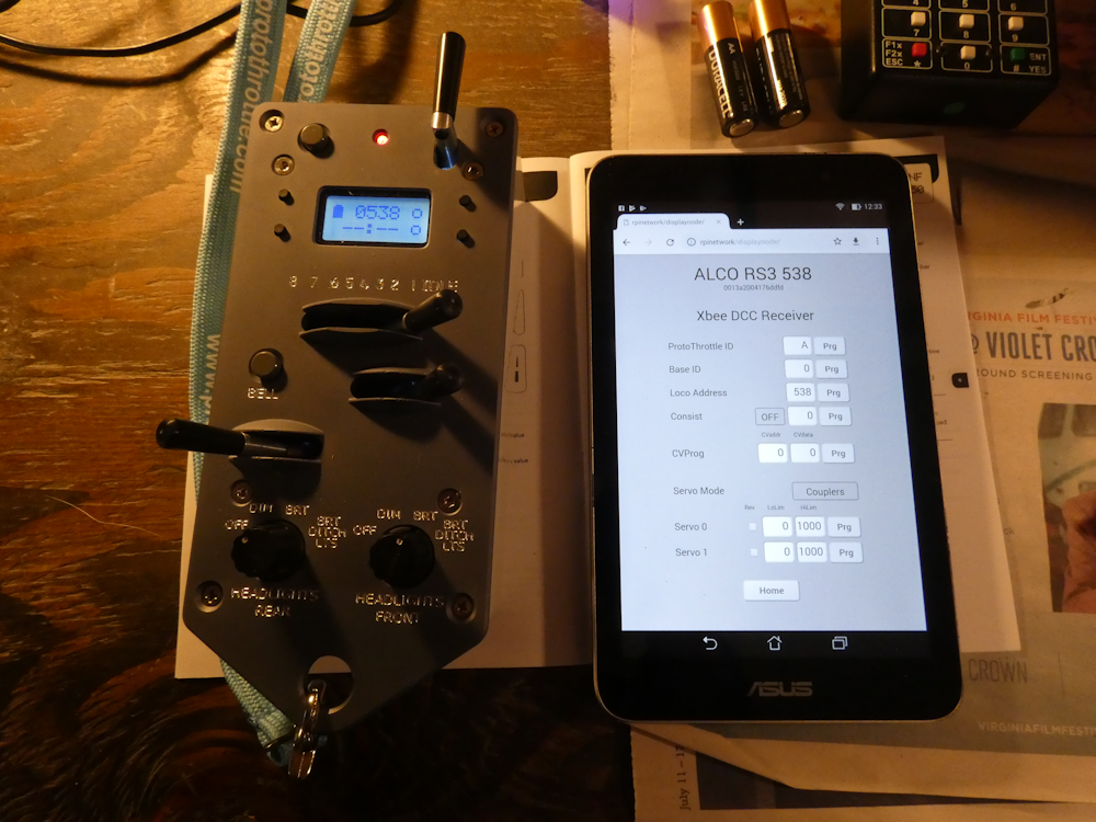
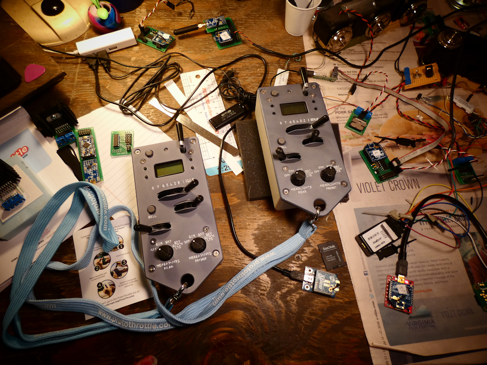
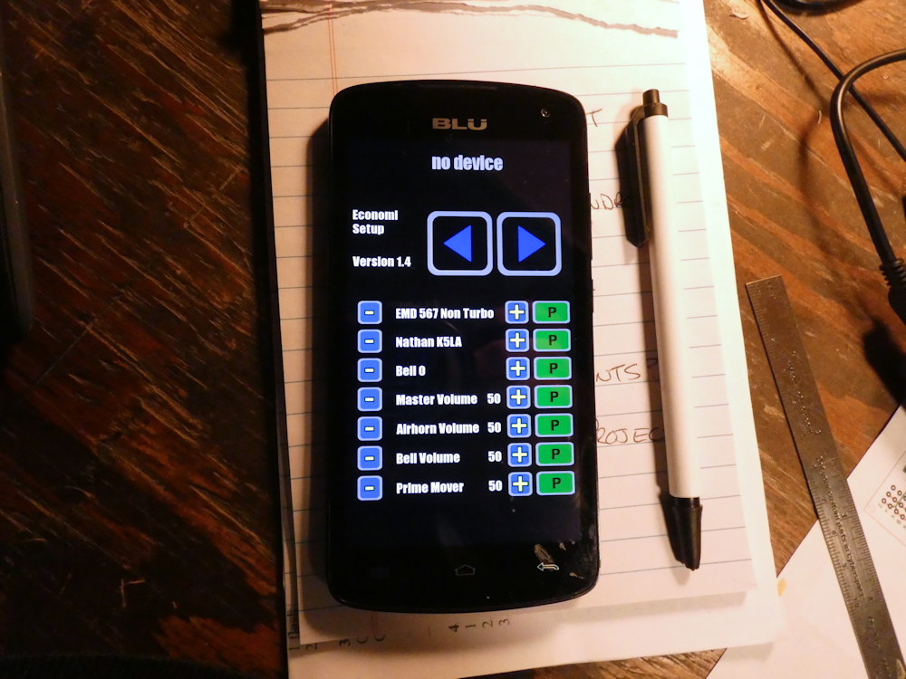
While I like Bluetooth ok, it’s not really meant to do control sorts of things. I mean, it will do them and all that and the phone I’m using has a decent range but it’s not really happy with multiple nodes. I also don’t like the phone for driving trains. I mean, it’s great for programming decoders, way way better than obscure CVs as shown below:

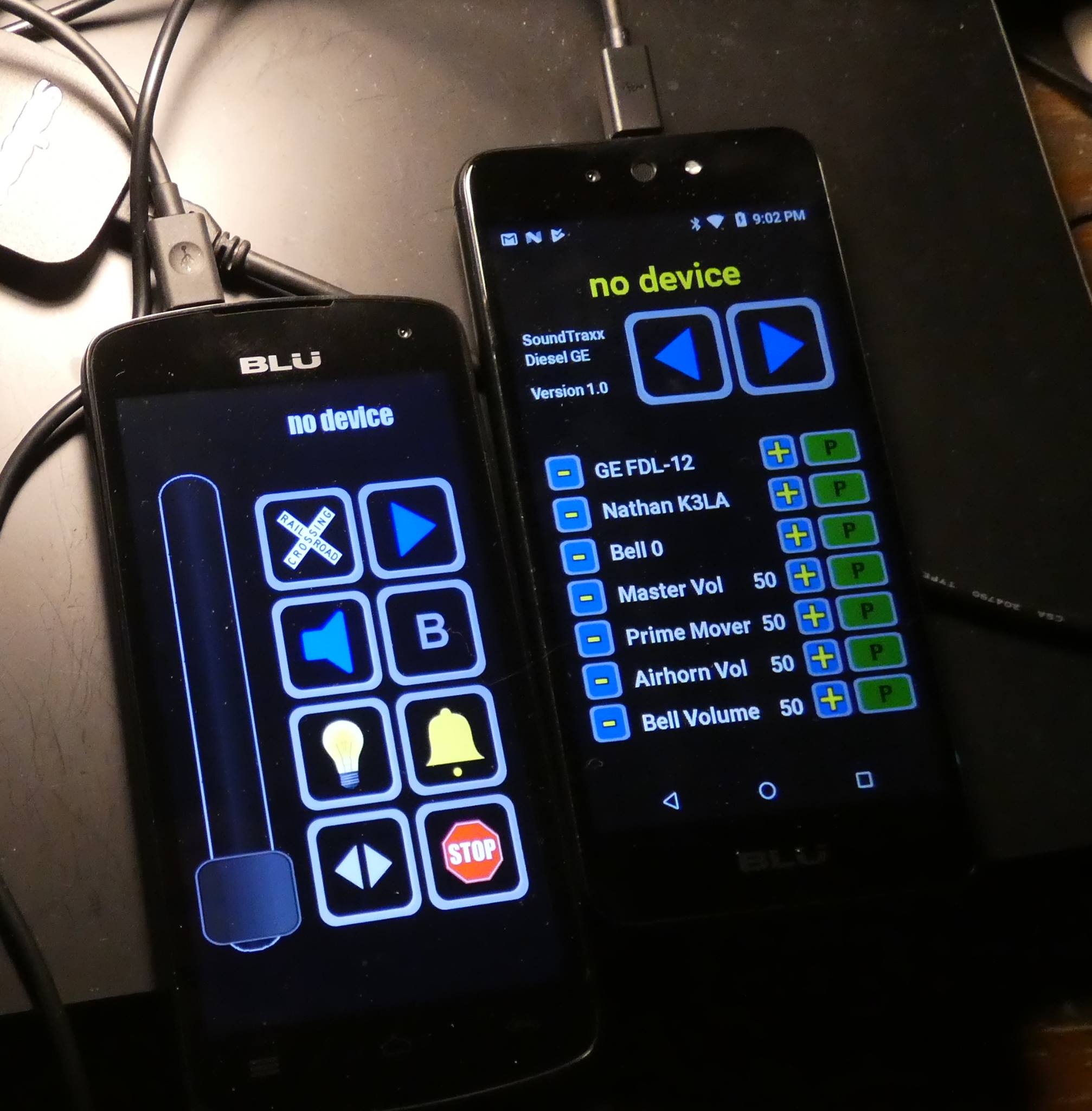
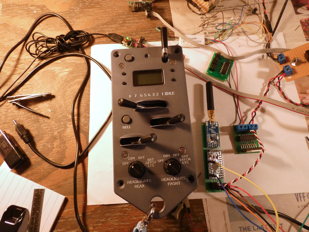
And if you are doing just general train driving its fine. But for switching or live steam on grades, it’s not so great to run a slider with your thumb. The live steam one was particularly difficult, you have to keep your eyes on the locomotive and also keep track of the slider. I found that to be quite difficult at times – I need a knob I can feel under my thumb. So I decided to start with Airwire since its very popular and they make a nice handheld unit with a knob.

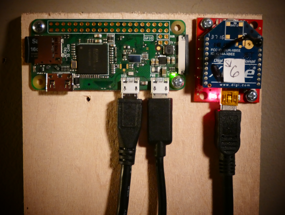
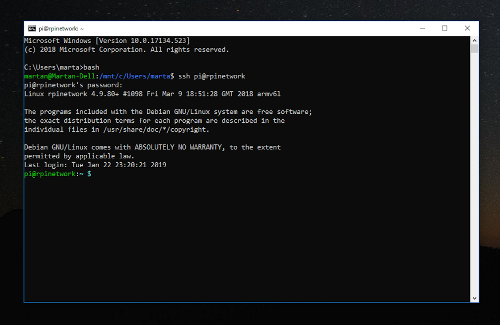
Going with Xbee Digimesh also frees up the phone side of things – I don’t need specific Android Apps anymore, a web app on my $10 raspberry pi zero will do everything I want from any platform, Android, Apple, PC, etc. Anything that can run a web browser will now be able to control things and more importantly, configure decoders and other things with nice descriptions and such. It also lets me implement the entire Rpi setup with Python. Everything is python, I’m using Flask and Apache on the RpiZW. There is a bit of Javascript in the pages but very little is needed, most everything is python. It’s very cool, you can log into the Rpi like any server from your PC to goof with code.

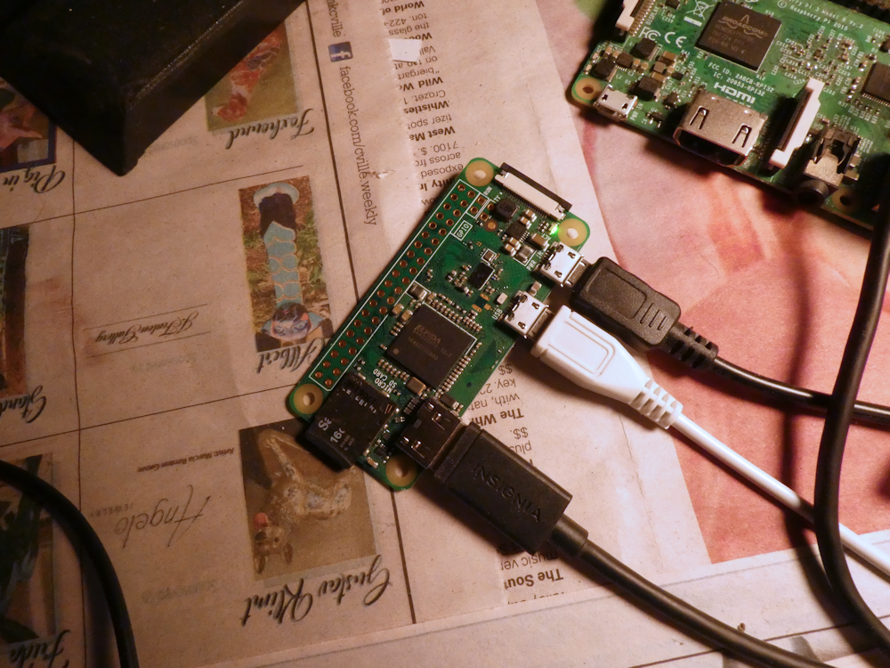
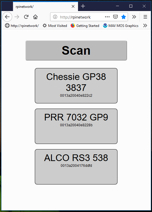
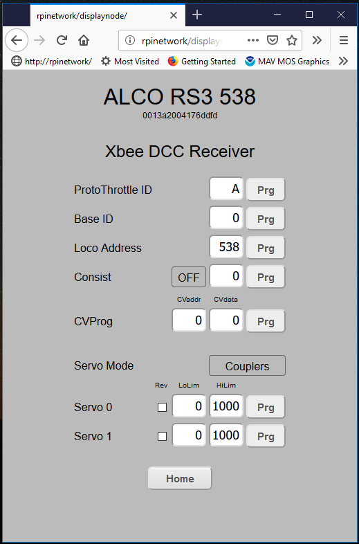
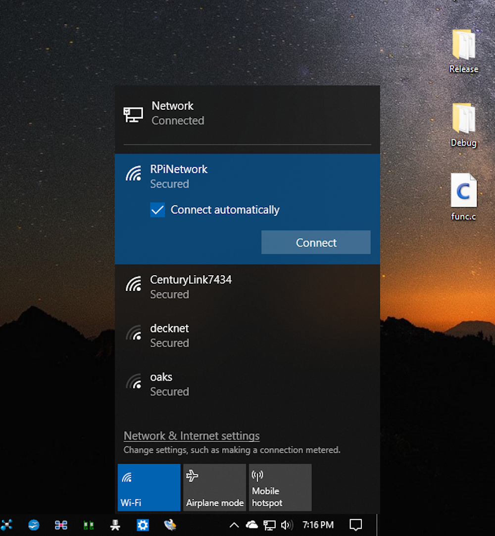
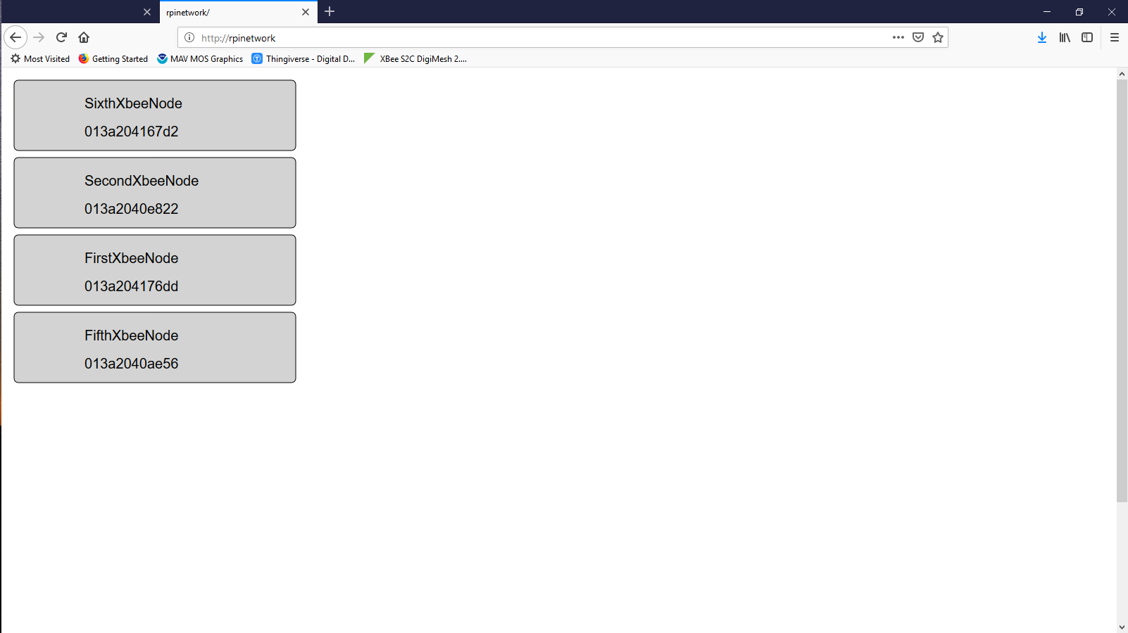
The Rpi Zero W, with the right configuration, can operate as a standalone Wifi Access Point with it’s own dedicated web server. (in this case, flask and python along with a little SVG for the web page interface). Just add the access point wifi to your phone or (his pic) your PC, and you can then display and configure any node on the digimesh network. Very cool. Here is a quick page I made up that does a network query on all Digimesh nodes it can find and displays a small box of info about each.


If you have a Raspberry Pi Zero W, I have a 16G disk image you can try out. It sets up the Pi as a standalone Wifi Network with it’s own web server and MySQL database and a few other options. I started on a page for it, not sure if I ever finished but I do know the RpiZW disk image is up there, you can download it and flash a 16G card for your RPIZW if you would like to do some poking about. It doesn’t display the above page but it has some basic handlers you can play with (its all Python)

Raspberry Pi Zero W Disk Image Info


Anyhow, this is just the beginning but it gives me a new set of toys to play with if nothing else. I’ll try to put together some sort of open source project for this once I get it working. The airwire modem is like $10, an Xbee is about $17 and the Raspberry Pi Zero W is $10 so this should be a relatively low cost control system.

I originally built this as an office for the RV Park but it doesn’t seem quite right in the role, so I made it a Post Office in my new town of Proffit VA. I’ve got it installed and wired into the solar grid.