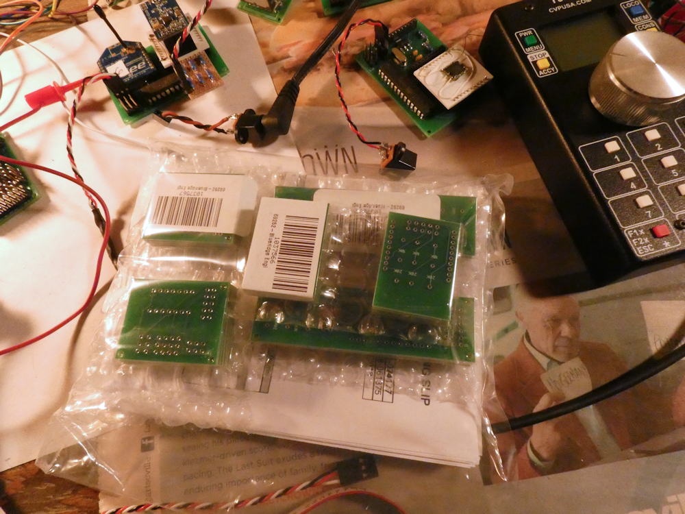
Santa brought me a bunch of circuit boards and other electronic goodies, so I decided to try some quick porting of existing code and protocols. I really like the knob on the Airwire Handheld but I much prefer changing the parameters of the DCC decoder with my phone. So for fun I refactored some code from my bluetooth receiver, added a CC1101 radio modem and now my phone can talk Airwire. Way more fun! So now I get the best of both- the big knob on the Airwire throttle and the nice color UI on the phone to change the DCC parameters. (Notice the big knob on the Airwire Throttle- I had a really nice Aluminum antique knob from another project so I mounted it instead of the plastic one that comes with it. Much better feel.)
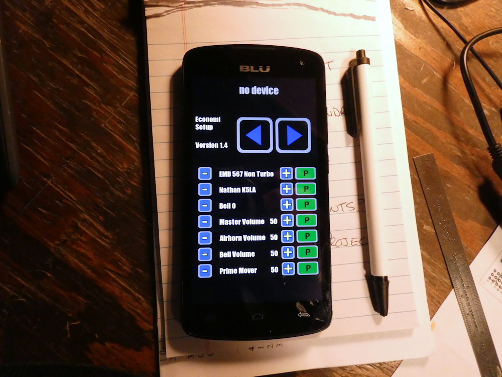
The phone will do it all now, I can also drive the train with the phone if I wish (probably not) plus I can setup all the other DCC parameters like the engine choice, the acceleration/decel, brakes, etc. All with plain text and pretty colors. Can’t beat that. I do have to add some parameter entries to the phone like the Airwire Channel number and the DCC address, but I’ll get to that soon.
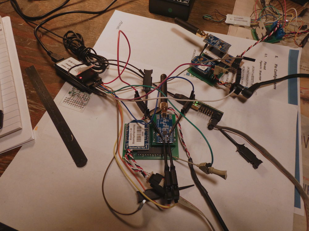
Above is the bluetooth/airwire transmitter side. For the most part, this is a complete design. The PC Boards require just a couple of tweaks but they are in good shape. I’m using the Bluetooth chip to intercept commands from the phone and then translating those into a logic level DCC stream. That feeds directly into the CC1101 radio modem which then talks to the Airwire receiver.
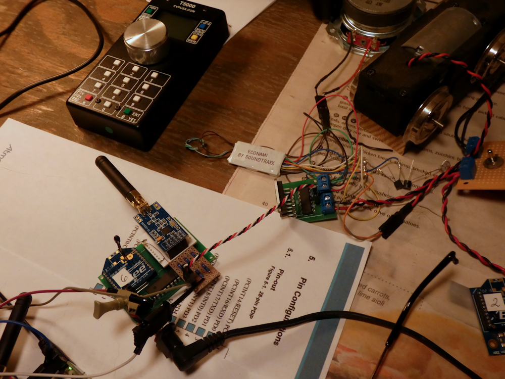
This is the receiver side. At the moment it’s just adhoc on the breadboard but I’m also working on a couple of smaller receivers. The DCC amp at the end combines the Battery voltage (or in this case, wall wart for testing) and changes the logic level signal into ‘real’ DCC. This drives an Economi (Soundtraxx) 2amp Decoder. The soundtraxx is just for testing, this will eventually be going into a GP38 with a TCSWOW 5 Amp decoder and 3300mah Lipo.
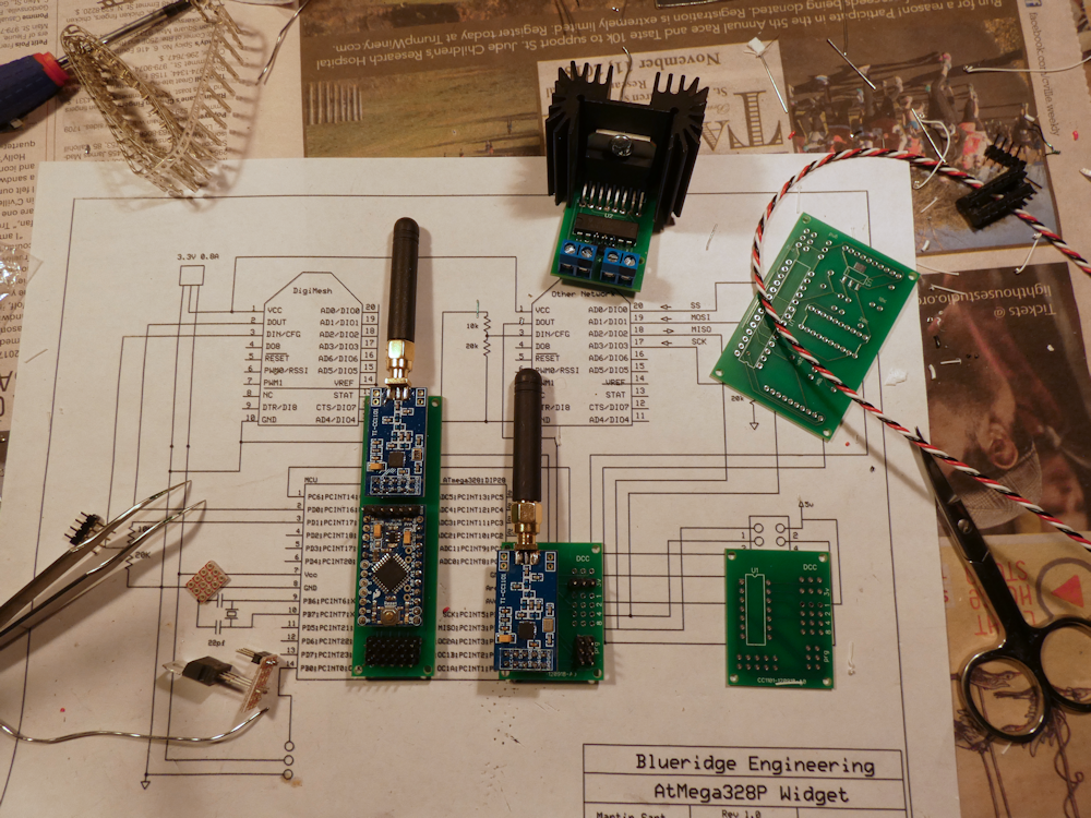
Anyhow, below are two of the receivers, one is the ‘deluxe’ version which contains a complete Arduino ProMini board, and the ‘minimal’ which is an Attiny24 design. These also are complete boards. The Promini design can be altered with Arduino Studio, the smaller one is not programmable, you use the jumpers to set the Airwire Channel.
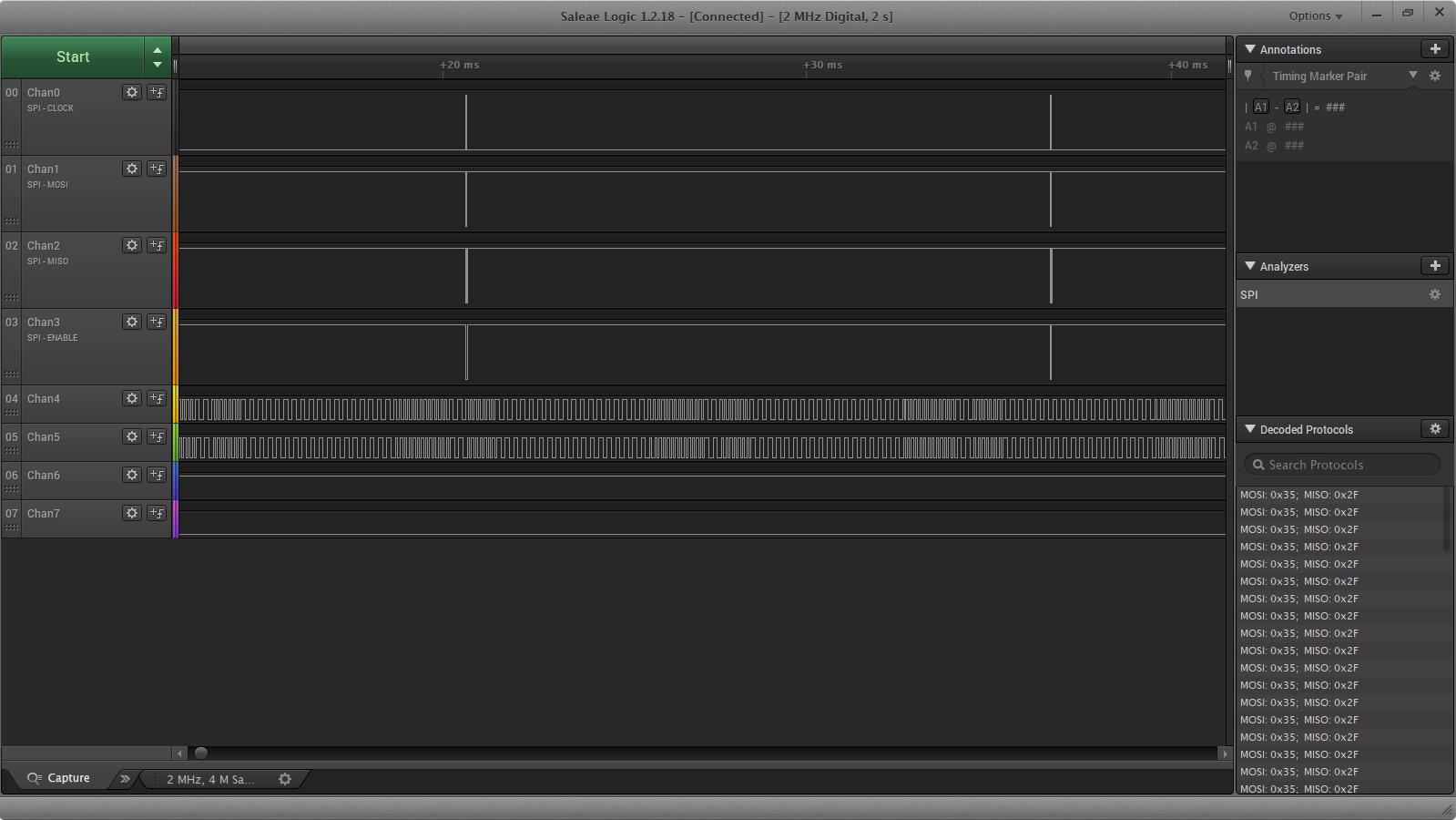
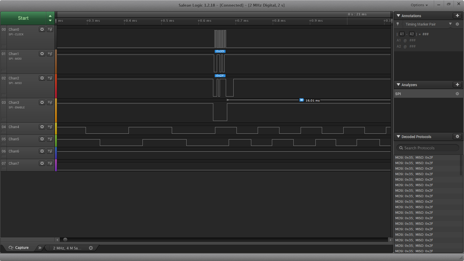
Here are a few images of the logic analyzer and what’s going on between the devices. The top four traces are the SPI line to and from the modem on teh transmitter side. The bottom two lines are the transmit side DCC signal and the receiver side- they line up perfectly. Just blasting DCC over the air is a pretty brute force way to do things but it does work quite well and is fairly east to duplicate.
