Electronics

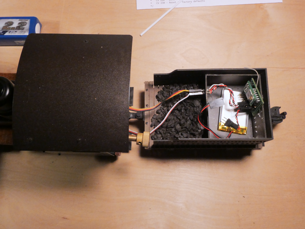
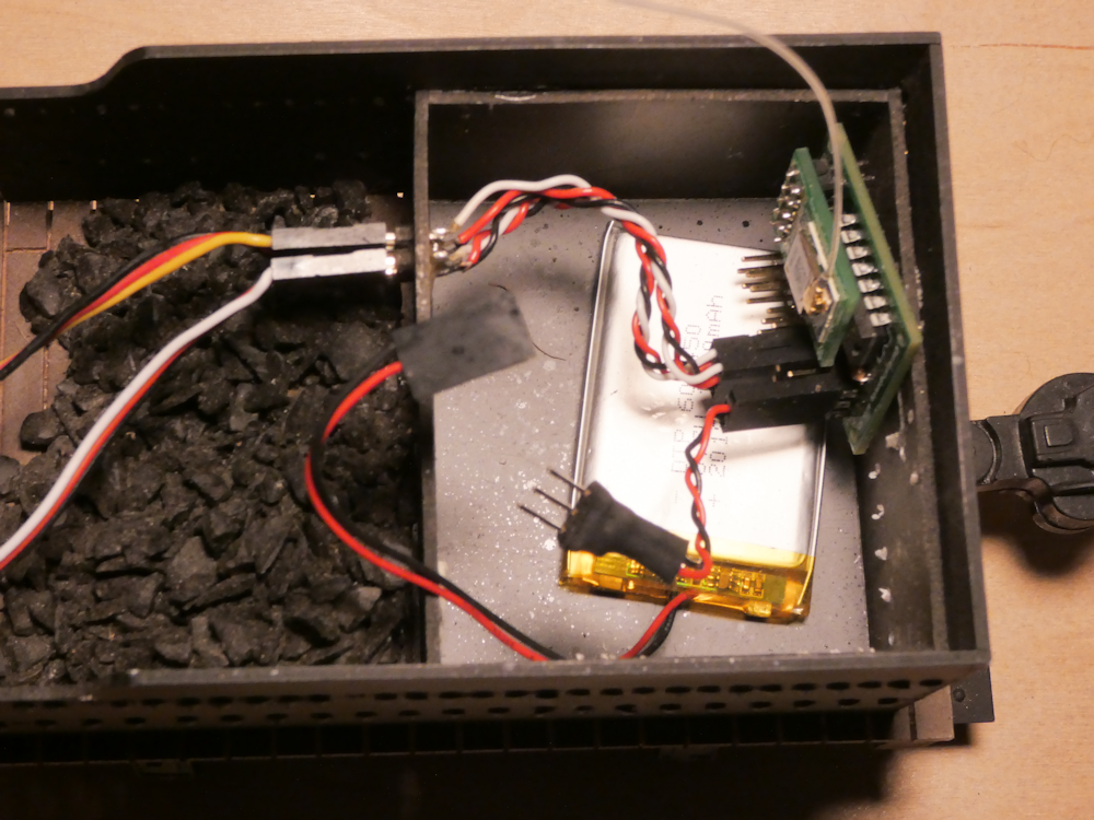
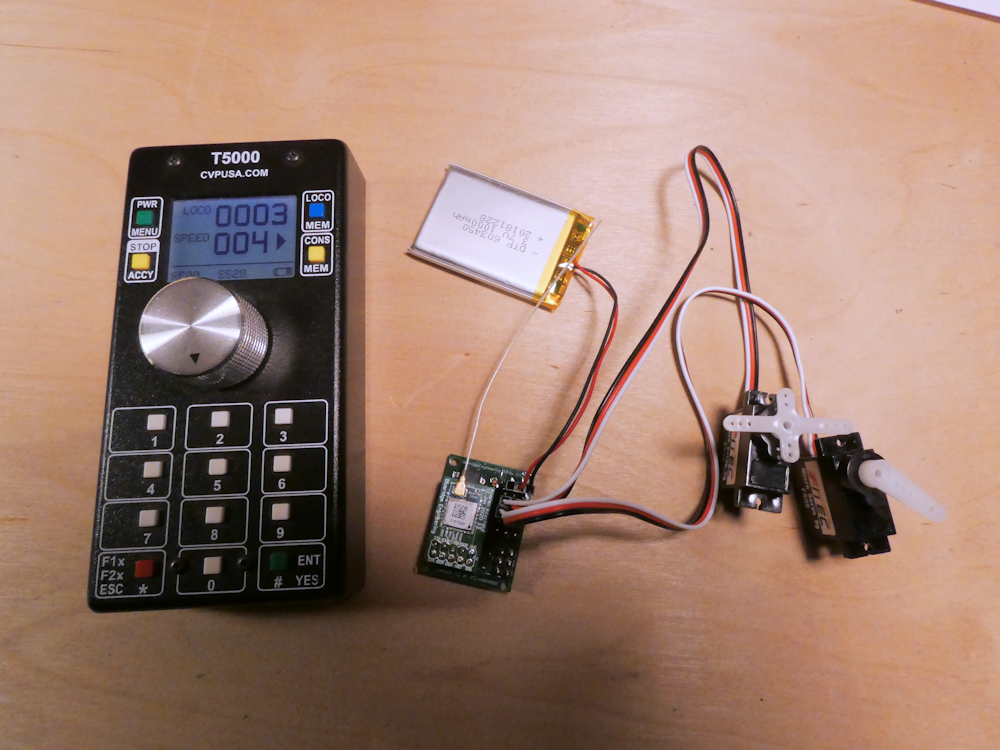
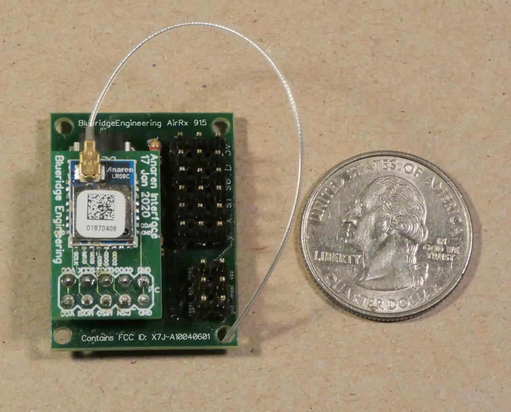
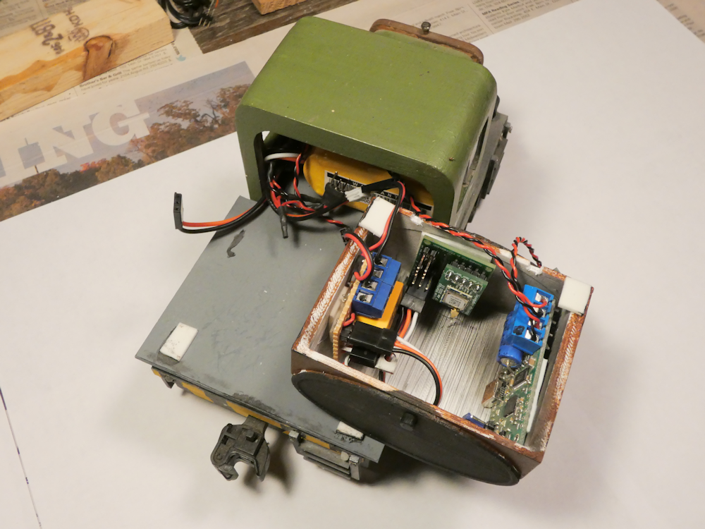
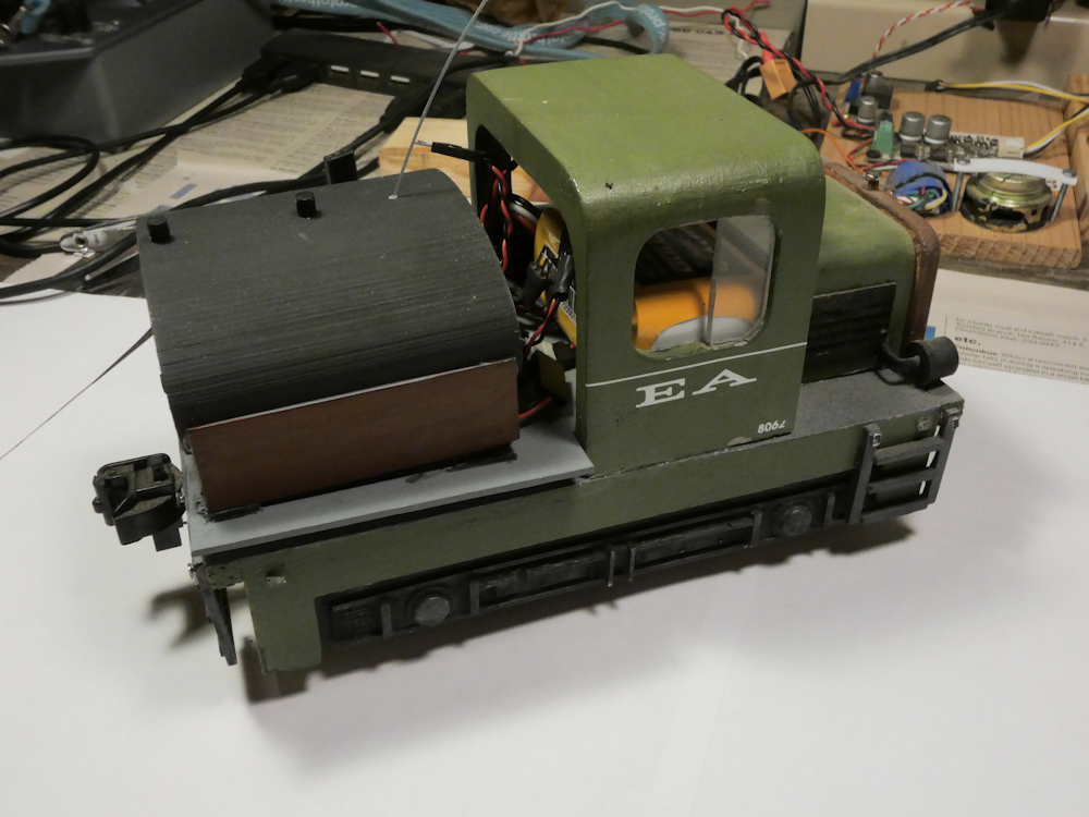
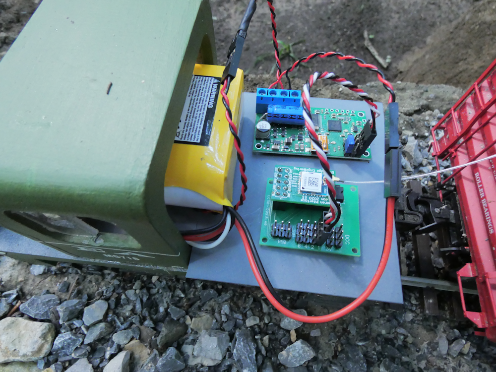
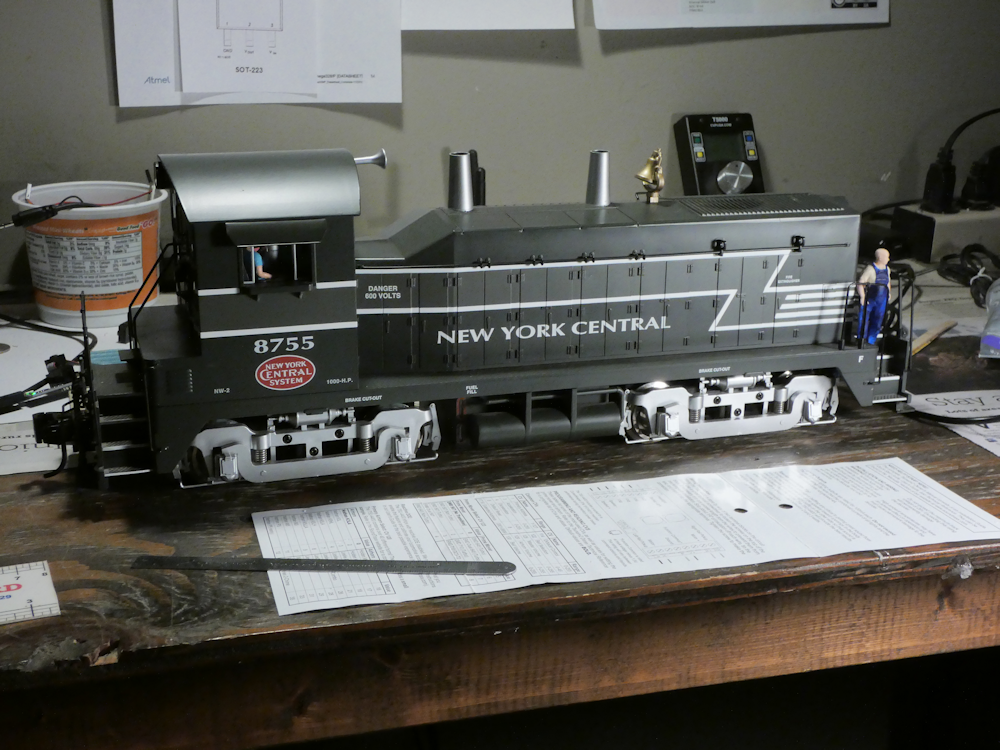
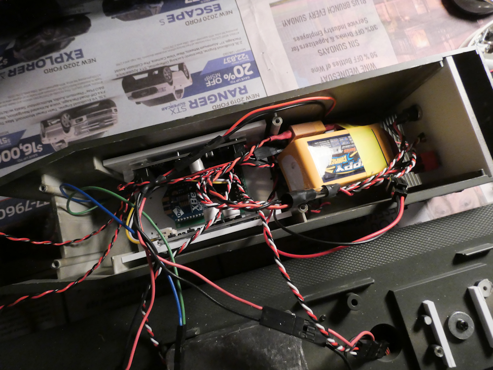
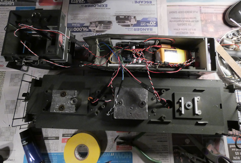
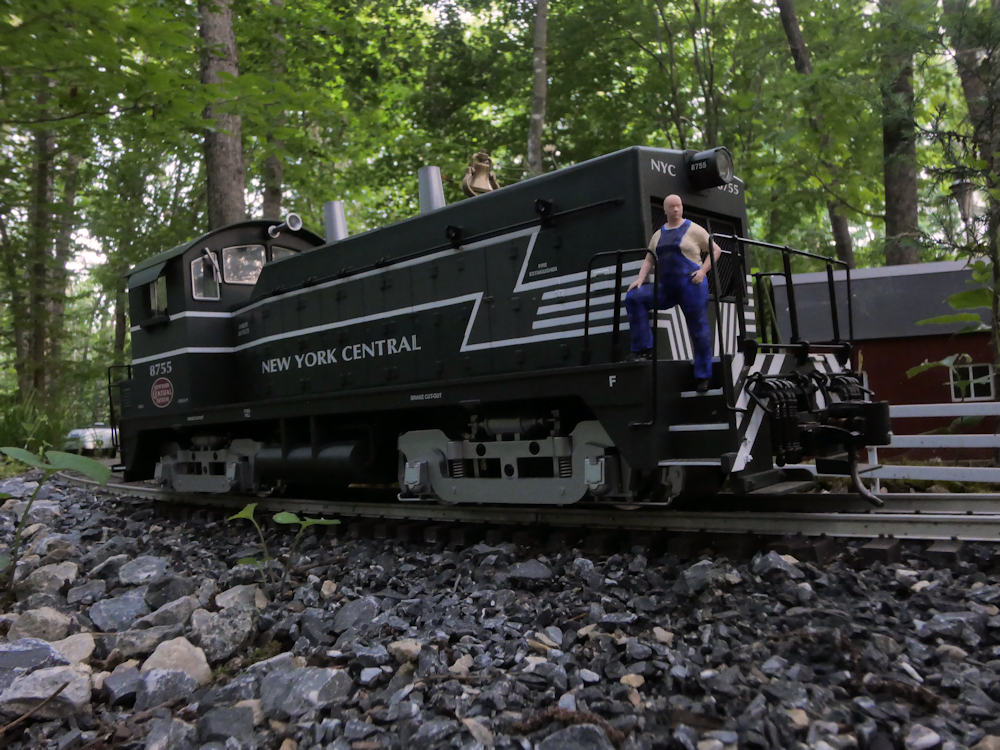
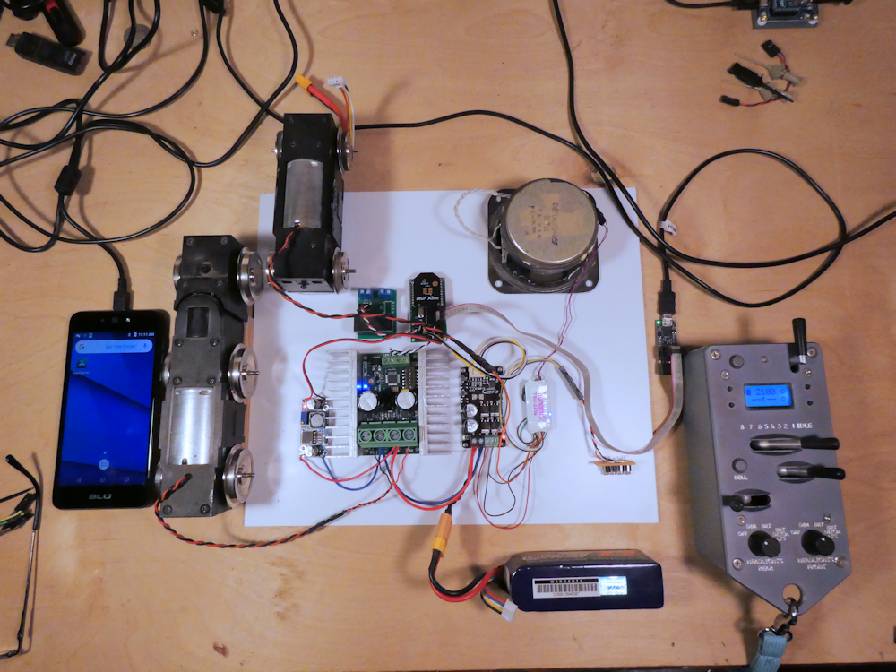
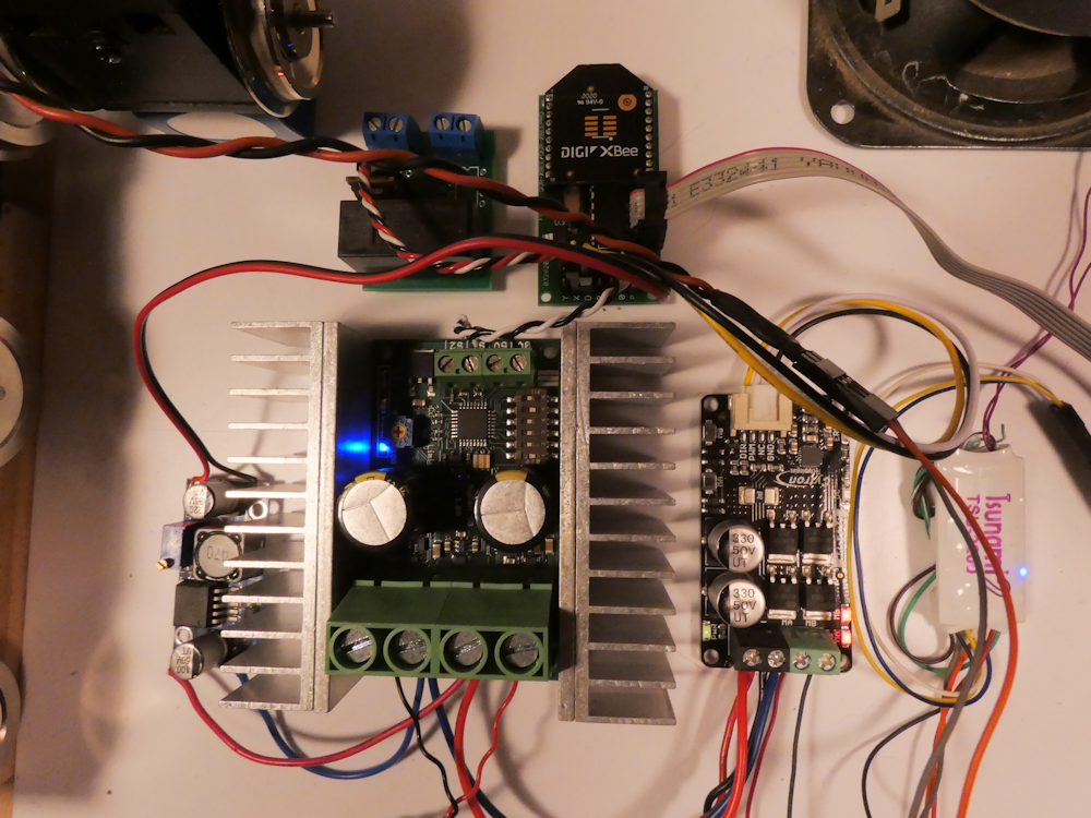
In my quest to drive ever larger locomotives, here is my latest development rig. It is designed for both very large motors and DCC. It can drive motors up to about 50A and can also supply about 8A of DCC. It consists of the Protothrottle Receiver, the Syren50 50Amp motor controller, a SoundTraxx TSU2200 DCC decoder, a Cytron Amp for the DCC, a 5v buck converter (to power the rx), a power relay and two motor trucks. One of the trucks is driven with the Syren50 and the other is hooked to the TSU2200.

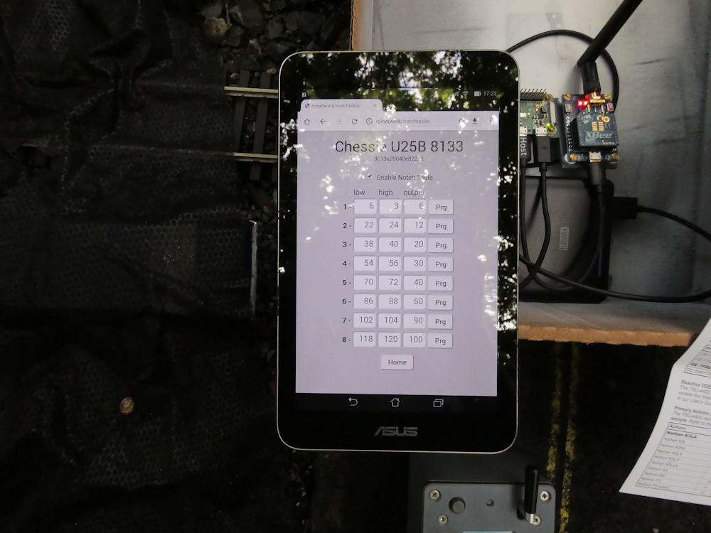
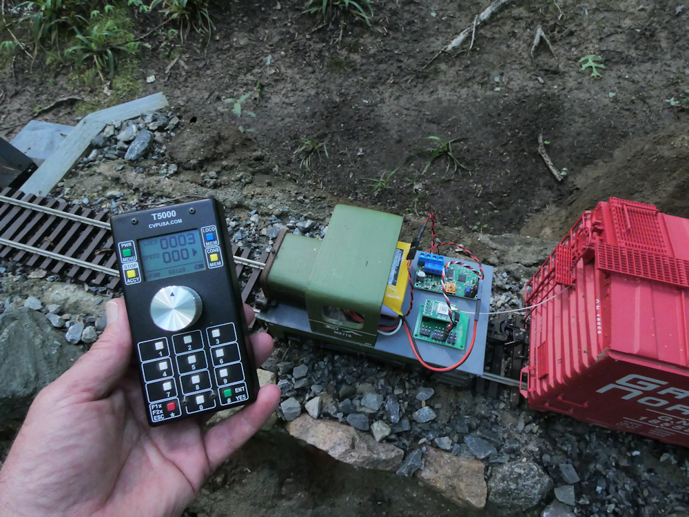
I am pretty close to a final release on this iteration. It includes a new ESC mode, PHYSICS, and four parameters for setting up acceleration/deceleration and braking with the Syren50 motor controller. The braking responds to the brake lever on the Protothrottle and has a variable rate. The brake function parameter sets which function code the brake effect reacts to. On the TSU, this is F11, so I’ve set that here to get the brake squeal sound out of the decoder.

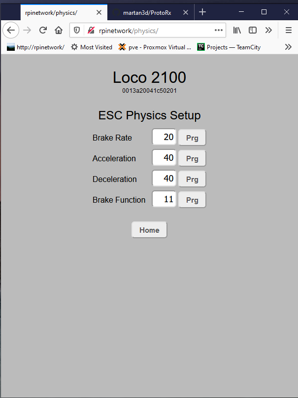
With the exception of the Brake Function Code, all of the values are in milliseconds. These represent an increment or decrement of one throttle step every X milliseconds until it reaches the value sent by the Protothrottle. Low values closely follow the PT, larger values take more time to reach the PT value. The brake rate is similar, however it is affected by the amount of deflection of the Protothrottle’s brake lever. The more deflection, the more brake is applied.

Here is a video of it in action. Note that the acceleration/deceleration of the large motor block, tied to the Syren50, differs quite a bit from the acceleration values in the decoder controlled motor truck. In actual use, these would be ‘tweaked’ so the DCC and ESC rates match.

Protothrottle Dead Rail Receiver

So it turns out the newest Digi Xbee3 network radios can do good ole 802.15.4 packets just like the older S1s and S2Cs. But one REALLY COOL thing they can do that the old ones can’t (ok there are two cool things, but I’ll get to the second) is they can talk Bluetooth BLE. At the same time as the regular Xbee network. And what is really neat about that is that the messages appear on the serial port, thus my application firmware can get these, interpret them and do STUFF. All sorts of stuff like actually control the throttle AND configure the module. Oh, and the second really cool thing is they have microPython built in too! Not that I know what to do with that now but it’s just really COOL 🙂

So, first pic is one of my Android phones (that I don’t have service on). It shows the connection to the Xbee3 via BLE on my little Android App. It was a bit of challenge to get the Xbee Library in there and there are still a few kinks that I need to work out (I have a love/hate relationship with Android Studio) but you can see on the second shot that I am getting valid Xbee Packets coming into my Receiver Firmware. Last pic is my setup (I have a Syren50 now)

So now I can have one receiver that talks to the Protothrottle and my phone at the same time. Sweet! I can configure parameters with the phone, or even drive the locomotive. I can also get data back to the phone (with the appropriate sensors), like speed, battery status, position, etc.

The original Protothrottle Receiver was able to control an ESC, but it just output throttle value as is, no manipulation. In some implementations this could cause abrupt changes in speed. So I added a new ESC mode, ‘PHYSICS’. This allows a standard center off ESC to now have a programmable acceleration and deceleration value. I also added a brake function that you can set to any DCC function code on the PT. This will allow you to drive a DCC decoder for the sound and lights, but actually control the motor with an ESC. There still isn’t any BEMF to feed into the decoder but I’m thinking on that one.

Fixed a few things and cleaned up a bit of code for a new firmware release on the AirRx. Here I’m using it to control a small live steam locomotive.

Below are a couple of shots of the electronics in the tender:

The electronics on the bench:

Short video:

All of the CV settings:

/*
 * Decode message packets here and do servos and config variables
 *
 *   CV 201 - Radio Channel 0-15
 *   CV 202 - DCC Address lo
 *   CV 203 - DCC Address hi
 *   CV 204 - Servo Mode 0=Steam, 1=couplers, 2=ESC
 *   CV 205 - Servo0 LowLimit Lo
 *   CV 206 - Servo0 LowLimit Hi
 *   CV 207 - Servo0 HighLimit Lo
 *   CV 208 - Servo0 HighLimit Hi
 *   CV 209 - Servo0 Reverse
 *   CV 210 - Servo1 LowLimit Lo
 *   CV 211 - Servo1 LowLimit Hi
 *   CV 212 - Servo1 HighLimit Lo
 *   CV 213 - Servo1 HighLimit Hi
 *   CV 214 - Servo1 Reverse
 *   CV 215 - Function Code for Coupler 0
 *   CV 216 - Function Code for Coupler 1
 *   CV 217 - Function Code for Output x
 *   CV 218 - Function Code for Output y
 *   CV 219 - On/Off Code for Output x
 *   CV 220 - On/Off Code for Output y
 *   CV 230 - Reset to factory defaults
 */

More info – http://blueridgeengineering.net/

I managed to get a bit of time between the extremes of heavy rain and oppressive heat we are having to do some real-world testing of my new consist feature. I’ve had a basic consist setup in the receiver for a long time now and if you run similar locomotives with the same decoder setup, it worked ok.

However I have two very similar looking but different Chessie locomotives. An Aristocraft U25B with a Soundtraxx TSU4400 DCC decoder and a USA Trains GP38 with a TCSWow 501. The Aristo U25 ran about twice the speed of the GP38 at the same PT notch setting. Lots of grinding and coupler pops, these two were not happy together.

I did not like the idea of custom speed tables and all that CV programming etc, so I decided to just intercept the notch/throttle and apply a custom value. Hence this feature.

This adds a table in the receiver that is enabled if the loco is a consist ‘slave’. You can program each of the notches as sent by the Protothrottle to a unique throttle value that is sent to the decoder. This lets you more closely match up speeds.

Above is my outside setup with a closer shot below. Yes, it’s in a cardboard box but it keeps the electronics in one place and is very portable! (the fold out card is for the TSU4400 CVs, I can’t ever remember them) I use one of those phone external batteries to power my programmer and a Asus 7 inch tablet to run the web app. Works well and the parameters are updated in real time.

In the following video I’m just letting the locomotives chase each other to test on how closely they are matched up. This also required that I change a few CVs in the U25B to dial in the acceleration and deceleration to more closely match the GP38. The GP38 is the lead locomotive on the left.

In the next video, I’ve built up a fairly heavy train. The tank cars are particularly chunky. I still have some small tweaking to do at notch 4, the U25B does not have quite enough deceleration dialed in. But it works well and looks pretty good. I see I will need one more programming aspect- a filter on the slave so that the bell and horn can be turned off. Right now, that passes through so I get two bells and two horns, sounds a bit weird.

Below are some screen shots of the web app interface. For the most part, the cosmetics are the same but I have refactored the Xbee message passing and screen refresh code to make it more robust. I’ve also added a way to set the Node Identifier in the Xbee, this is a 20 character ASCII string that I use as the locomotive name. I used it to set the name of the Protothrottle to ‘Protothrottle’ since it comes from the factory as a blank. I would like to access more of the PT innards, particularly the configurations so I can save and load them on the computer, but that doesn’t seem to work in the current PT firmware? I would hack on the PT code but I like having a unit I ‘use’ and a ‘development unit’ to experiment with but I don’t have a spare $500 right now. Anyhow, note that these are screen grabs from my testing inside on the bench, not the above outside consist testing. For reference, the name at the top is the Xbee Node ID and the number under that is the mac address of that Xbee.


Boards and Software are available at:

Blueridge Engineering


The production boards are in test now. They came out very well. Very small and compact, no errors or blemishes. As mentioned in previous posts, this is an Airwire Compatible Receiver that uses the Anaren Chipset and matching antenna. It gets a good 100ft range and can be programmed to listen to any of the 16 Airwire Channels.

The second picture above is my Protothrottle to Airwire interface. This is still a quasi-pre-production sort of board as I don’t have the funds to re-design it at the moment but the circuit design and firmware are in good shape. It has some expensive parts but I’m getting very good results so far and have enough boards to build six or so.

The idea here is to get everything to play together. The Protothrottle on dedicated receiver boards and also allowing Airwire compatible boards to work as well. I’d add Revo to this but I don’t have one and they seem to be quite proprietary so would have to be reverse-engineered.

Anyhow, as far as the AirRx is concerned, in addition to passing the DCC signal from the Airwire T5000 (or my Translator) out to a power amp, it can also control two servos and two digital outputs. In the photos above, I don’t use DCC, instead I have it configured to use the servo output to drive a Pololu electronic speed controller (ESC). I have also configured one of the digital outputs to control a relay for the lights. Everything is mounted in a 3D printed ‘oil tank’ on my home made critter thing for testing.

Some more info can be found here: AirRx Receiver


This is a project I actually started about 2 years ago. I put it on the back burner when I got involved with Protothrottle development and it has languished in my electronics stash until the last few weeks. This is an Attiny driven Airwire Compatible Receiver. The board in the photos above is a development board, and as such has a few jumpers and mods on the underside. The production board will be quite a bit smaller and more compact (and no cuts or jumpers!).

I’m using an Anaren daughterboard for the radio modem, this is made by my colleague, Darrell Lamm, who has done a tremendous amount of R & D on these CC1101 radio modems and chipsets. These are really nice boards. They are also quite small and so perfect for this design.

I have taken the functionality of my Protothrottle and original AirMini Receiver designs, optimized the code and squeezed it down to a very small footprint. Although this is still in the test phase, I am quite happy with the results.

This board has the following features:

  • Compatible with the T5000 Airwire Transmitter
  • Compact size – 26mm x 34mm
  • Programmable using CVs
  • DCC Output up to 10A (with optional motor drivers)
  • Two digital output lines that can drive relays, etc, assignable to any function code 0-28
  • Two Servo Outputs that can be used in three ways:
    • Live Steam Mode – servo one follows the throttle, servo two is direction
    • Electronic Speed Control Mode – Servo one controls a ‘center off’ ESC
    • Coupler Mode – Trigger two servo controlled couplers

Here is a list of all of the programmable options for this receiver:

/*
 * Decode message packets here and do servos and config variables
 *
 *   CV 200 - Radio Channel 0-15
 *   CV 201 - Radio Power Code
 *   CV 202 - DCC Address lo
 *   CV 203 - DCC Address hi
 *   CV 204 - Servo Mode 0=Steam, 1=couplers, 2=ESC
 *   CV 205 - Servo0 LowLimit Lo
 *   CV 206 - Servo0 LowLimit Hi
 *   CV 207 - Servo0 HighLimit Lo
 *   CV 208 - Servo0 HighLimit Hi
 *   CV 209 - Servo1 LowLimit Lo
 *   CV 210 - Servo1 LowLimit Hi
 *   CV 211 - Servo1 HighLimit Lo
 *   CV 212 - Servo1 HighLimit Hi
 *   CV 213 - Function Code for Output x
 *   CV 214 - Function Code for Output y
 *   CV 215 - On/Off Code for Output x
 *   CV 216 - On/Off Code for Output y
 */

In the pictures and video, I’m controlling a Pololu 18v7 ESC motor controller. The Pololu has an option for a 3.3v BEC (battery elimination circuit) so it only takes two boards and a 2 cell lipo (7.4v) battery to drive my little test critter. I took it out to the layout to do some range testing and was quite impressed. With the T5000 set to transmit power ’10’ (full) I am getting a good solid 100ft. It may actually be a bit more but this is as far as I could go easily. Below is a video of the range test:

And a more close up video:

Here is my latest project – Protothrottle Dead Rail for a USA Trains NW2. Somehow I managed to squeeze everything into this little fellow but I did have to skimp just a little on the battery, it’s only 1300mah. But that’s fine for a switcher in my tiny little industrial yard.

It has a SoundTraxx TSU4400 in it, which is a really nice 5A sized DCC decoder. It’s ease of programming and the function outputs add to the great sounds. It also has some neat features in it including a 7 band EQ and reverb effects. One other thing it lets you do is ‘detune’ the engine sounds some- I took it down 100 ‘cents’, adjusted the EQ a bit and now have a good solid bass ‘thrum’ sort of effect. Pretty cool.

For this install I also did some software development to finish off the coupler mode for the servos. I have these set up on the Protothrottle so that the Aux button controls them. If the direction is set to forward, the aux button controls the back coupler, if it’s in reverse, it controls the front one.

Above are a couple of shots of the interior, I had to build a special little ‘cradle’ to get everything to fit. On one side is the Soundtraxx Decoder, on the other is the 10A motor driver. In the center is the Xbee Receiver. The battery is a 1300Mah 14.8v Lipo. There is also a small buck converter to power the Receiver and Servos at 5v but it’s under the battery so out of view here.


This one shows the servo and couplers. I 3d printed a servo/coupler sort of mount that came out quite well.

Good shot of it out on the layout with my 3d printed guy on the front.

Above is a quick video of everything all setup and running. Took me a while to tweak all of the parameters and sounds and assign them to the PT buttons but I really like the result. I have the acceleration and deceleration dialed in and enabled the brake. The couplers are triggered by the aux button and I’m using F12 for that so it already has the coupler sounds paired with the servo movement (more or less). I forget the actual horn sample I’m using but I watched a couple of youtube videos of NW2s and this one was pretty close. I mapped the engine start (F5) to the bottom LCD button and ‘radio chatter’ (F22) to the top one. It still needs a bit of tweaking but I’m very happy with how it came out.