Other Stuff

u25B-MainModel

I picked up a cheap Aristocraft U25B in Chessie paint the other day and have been taking it apart so I can rebuild it. The idea is to get from the toy like unit I have into at least a semi-scaled sort of model. The photo above is the closest prototype image I’ve found to what is depicted with this Aristocraft rendition. So I’m stripping it down to the base parts with the idea to install my control system, batteries and sound. And of course, a bit of paint and detail work- it is a bit cheezy with the cast color parts. Yuck. So anyhow, I’m getting there. Below is an image of the original model. More in a later post.

chessie

PCB as Art?

micro

I’ve been doing quite a bit of PCB design these days, here is a version of my controller board, the ‘microwidget’. It’s quite compact. I have not had any made yet but I thought it came out really sort of, well, neat. Like art kinda.

All total I have about five or six small circuits for doing control networks- specifically for large scale model trains. DCC input and output, servo control, DC brushed motor control, reversing relays- all via Industrial strength Xbee Network wireless.

I’m also thinking of making an apt-get debian package to install JMRI on a RPi 2 and gitlab for my code. Hmm.

I think I need a Kickstarter 🙂

master

P1040664

Here are the final two prototypes. The master obviously connects to the Prodigy Express and sports a long range antenna for max transmission power. What I’m thinking here is this is the module that will be connected to my RPi 2 which I am planning on running JMRI on. The Pi 2 will also have a long range wifi antenna on it so I can use it to source web pages to my phone and tablet. My standard handheld design is what I actually use to drive my trains with.

The second pic is the client. This one is fairly comprehensive and has quite a few parts but I use it as my standard prototype rig. In addition to the control board, it also has an (expensive) Pololu 18v7 motor controller and a current sensor. The DCC output stage is the board with the large chip beside the speaker. All it is used for in this incarnation is to drive the Econami Diesel DCC decoder which powers the speaker on the right.

Here are all the parts labeled, you can click on the picture for a larger version-

client-small

dcc

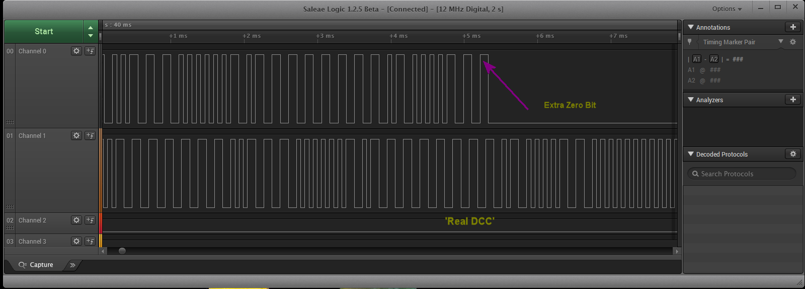
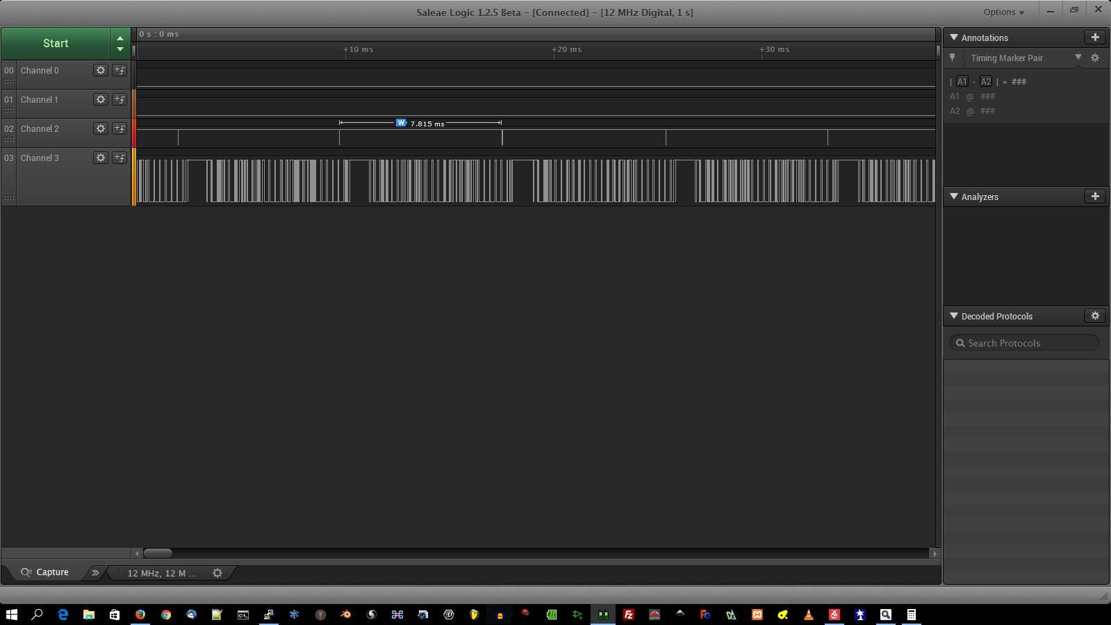
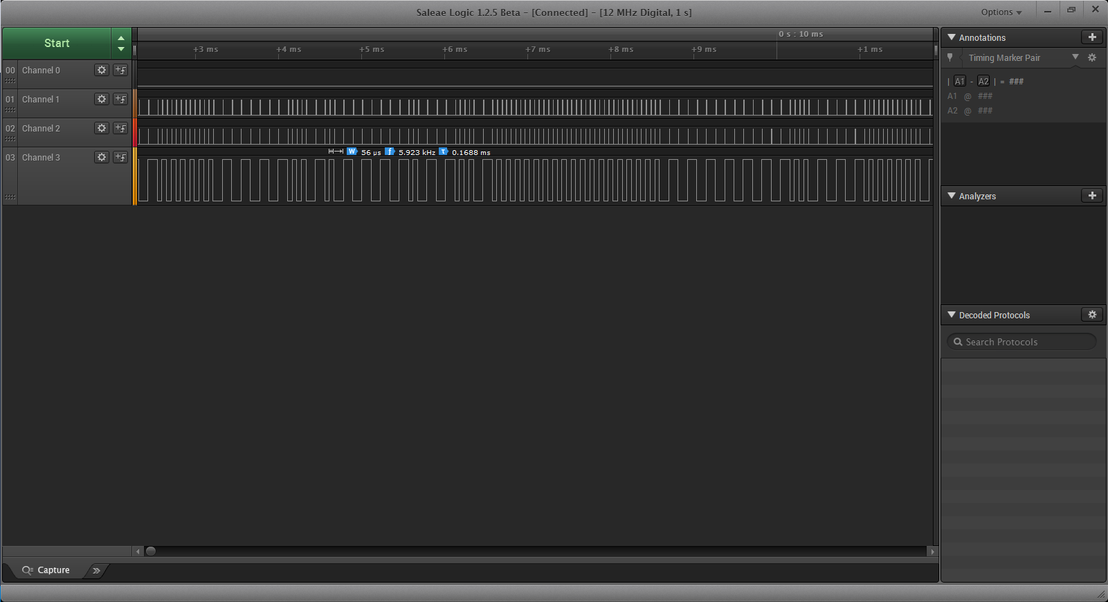
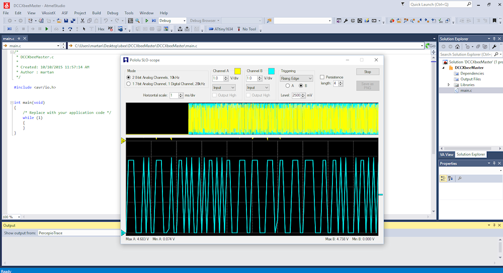
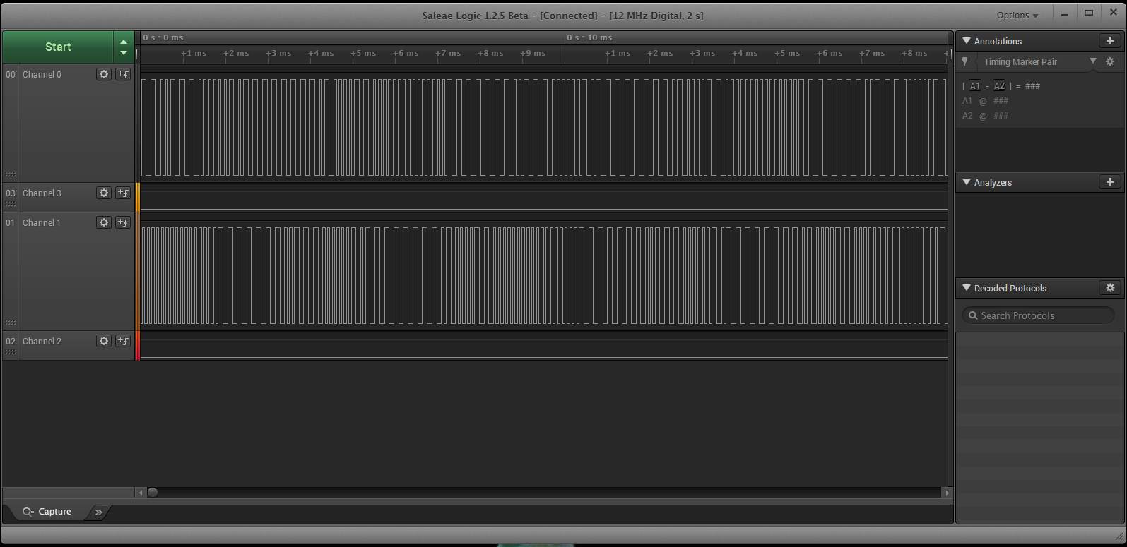
Well, I didn’t like some things about the DCC output state machine in the last post, the one with the (wrong) zero bit on the end so I refactored it and now it works mucho better. I took the background scan timer down to nothing so it would spit out DCC as fast as possible, this is the trace. The top trace is the rebuilt DCC, the bottom is the output of the Prodigy with just the default 003 loco address, albeit set to 128 step mode. Aside from the lesser number of preamble bits I’m sending they are the same, well within a microsecond or two. I am running this on an Attiny1634R-SU which is the 2% clock. Costs a few pennies more but worth it over the regular vanilla chip which is 10%, a bit loose.

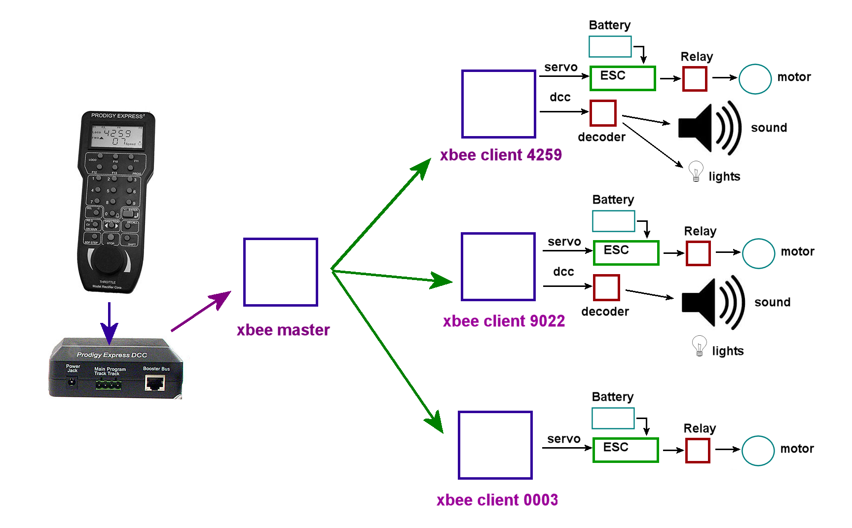
I think the diagram in the last post caused a bit of confusion. Suffice to say I am just breaking apart the components of DCC and the subsequent ‘decoders’. I find the term ‘decoder’ somewhat problematic, I would refer to them as ‘clients’ with the DCC ‘booster’ or ‘cab’ as the ‘master’.

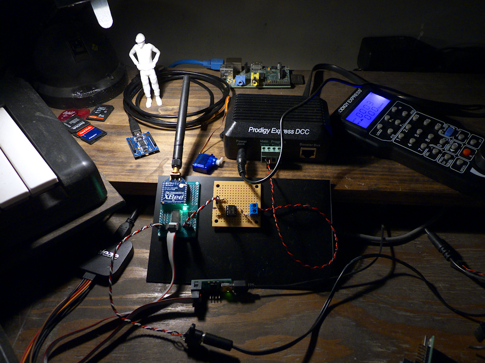
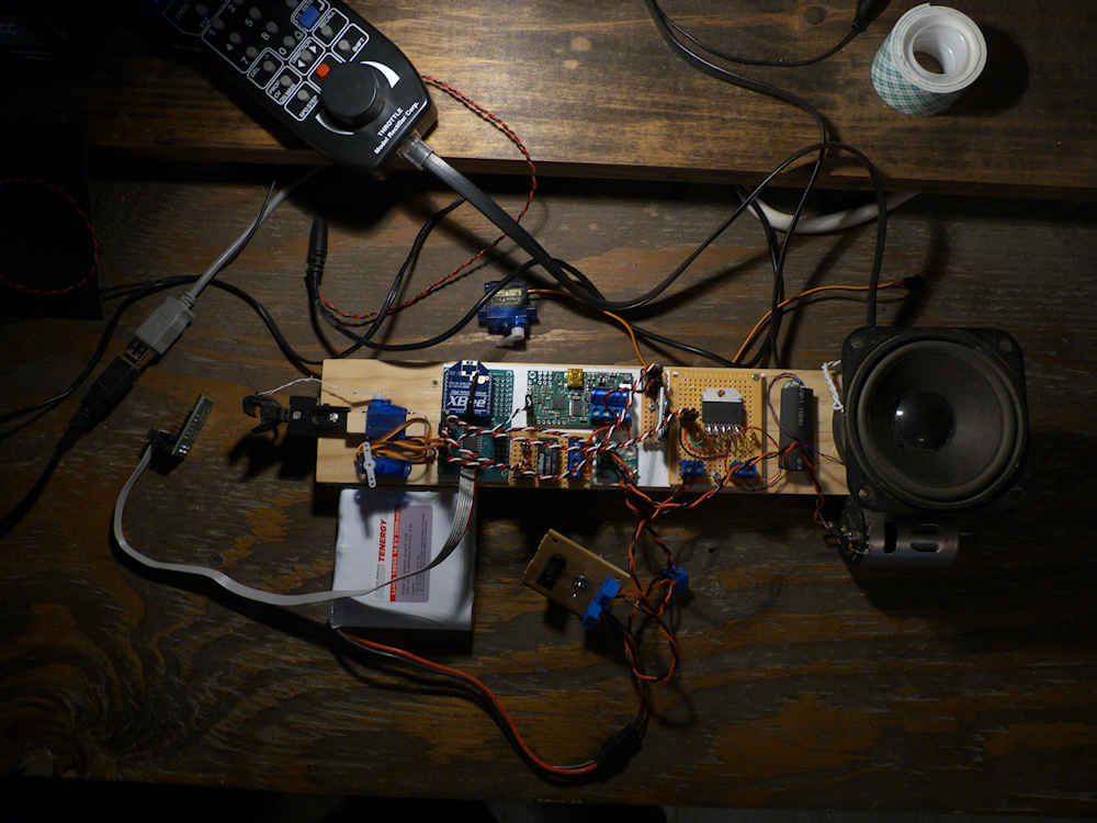
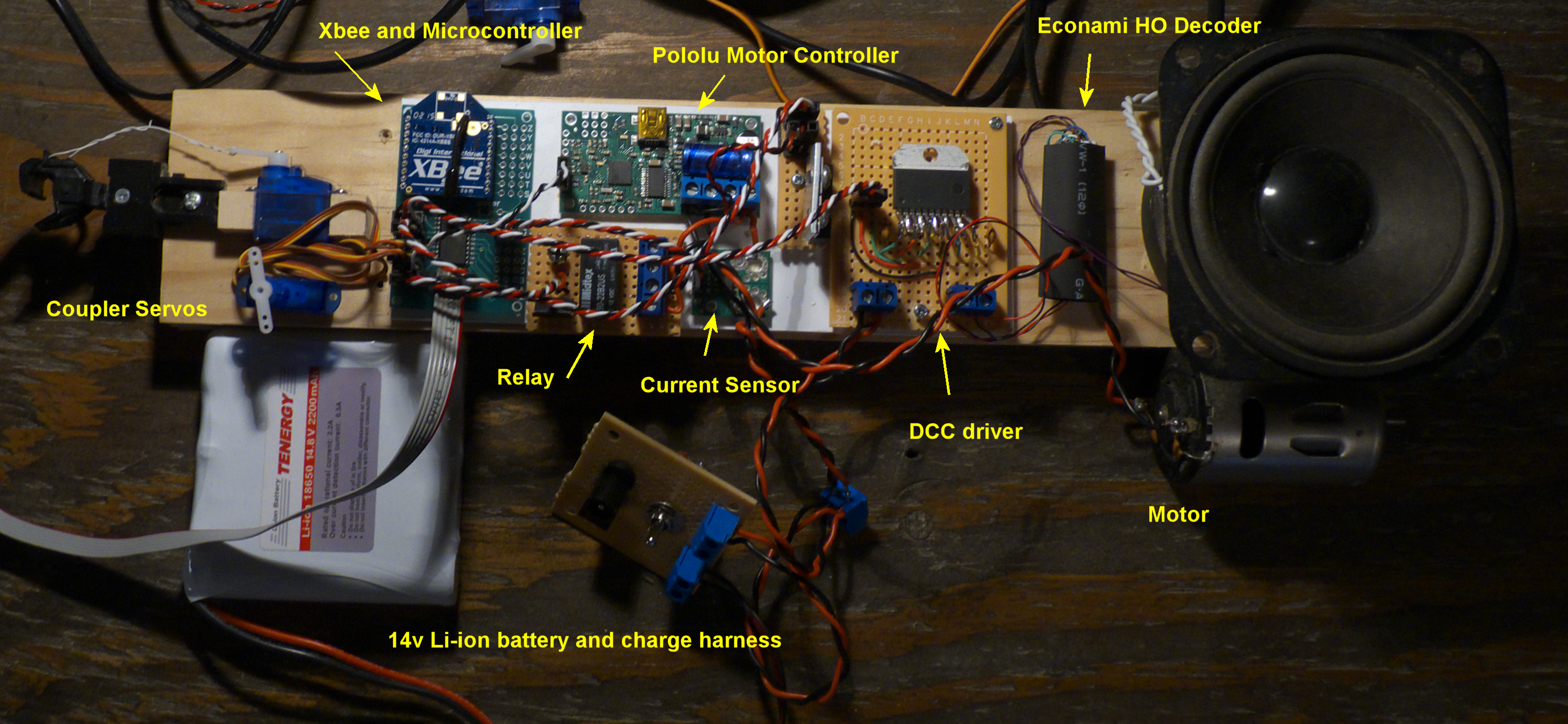
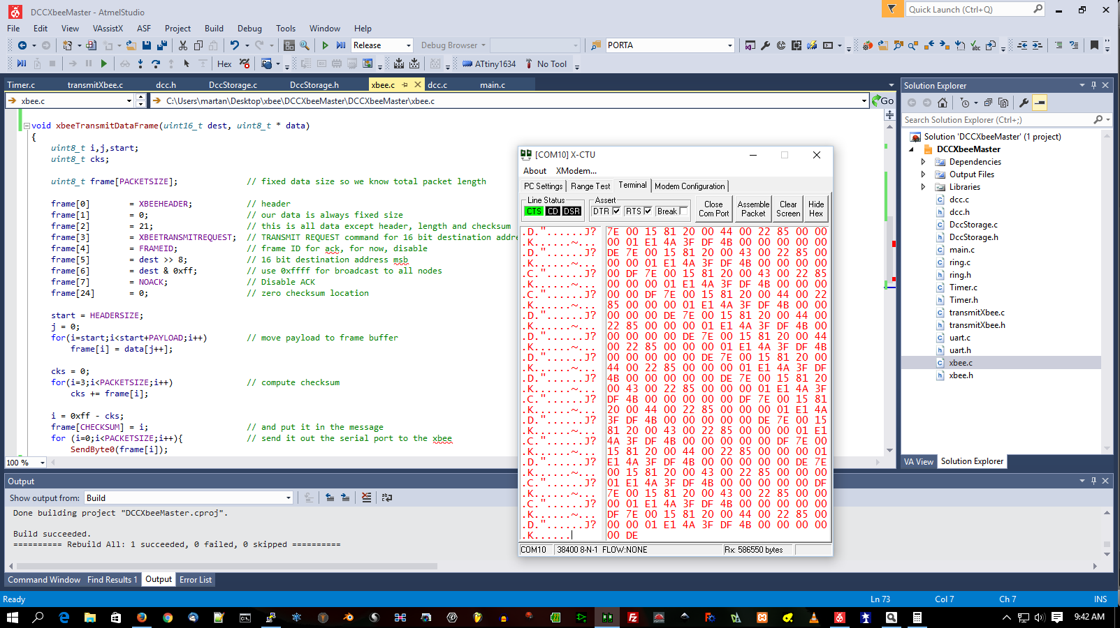
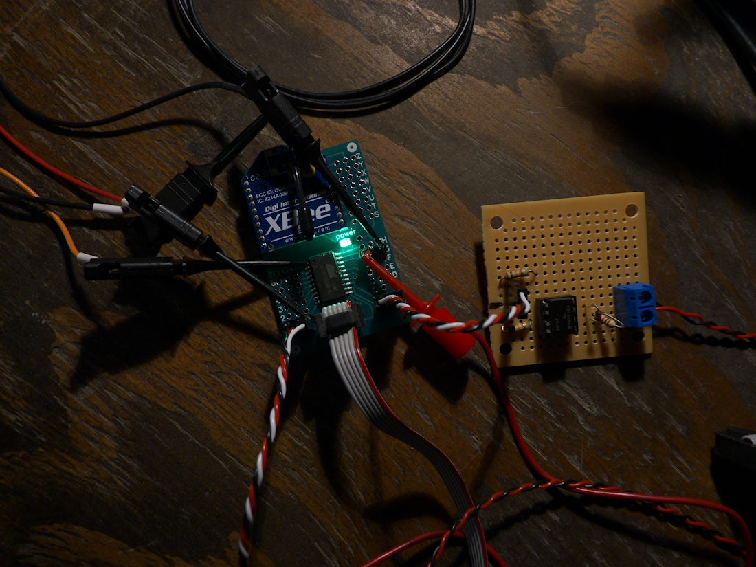
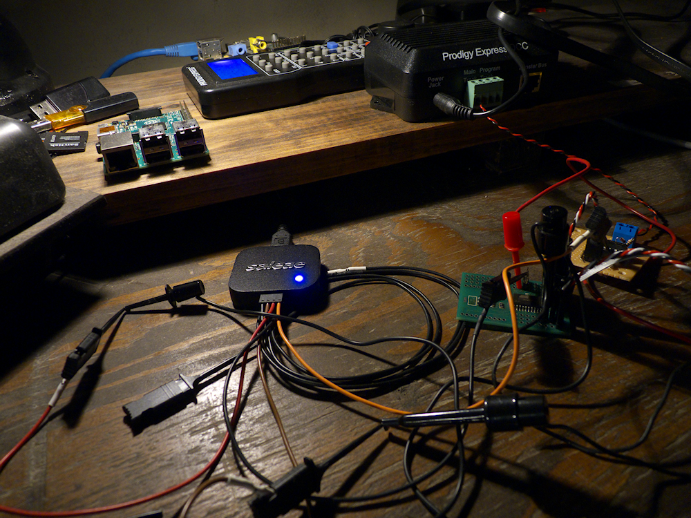
Anyhow, one of the things I do not like about DCC is the power aspect. DCC is sort of a bastard child of both power and data packets which makes messing with it more difficult. I realize that is really important when you carry power on the track but I don’t want to do that. I want the compatibility with DCC accessories and JMRI but I want to run battery power (or maybe steam one day) So I am chopping the power part out and siphoning off the data packets, sending the data out via xbee and rebuilding them on the client. The client takes the battery power, injects that into the data part and out comes DCC. I don’t need much in the locomotive that requires DCC per se, except possibly sound but I am interested in choosing routes via something (JMRI?) and setting turnouts (accessory decoders?) and signals and things like that too so I want all this to work.

Oh yeah, another aspect of DCC I’m finding I don’t like is the slam-bam sort of thing. Well, ‘not like it’ is relative I suppose, it’s probably the easiest one and most ‘organic’ of the protocols. Constantly send everything as fast as possible and you are at least sure some are getting there, right? So I’ve also, sort of, modified this at least over the air. This keeps network traffic low. I currently have only one priority queue in the master, I think I may have to expand this to two later one. A ‘hi’ priority for the locomotive situations and a ‘low’ for other things? Dunno yet.

diagram

A diagram of what I’m working on. Not shown is my prototype battery powered handheld, it would be (in addition to or to replace) the master in this diagram. 300ft range between the master and any client node, 250kbs.

I have about 80% of this working as indicated. I’m still coding up the Client DCC output state machine. It’s almost there but I think I’m off one bit at the end of the message. Hmm. Also, I have not yet tested the LMD18200 driver that will power the DCC out to drive the decoder, so that’s another step.

The weak link to me is the purple arrow between the prodigy and the base station. Right now, I have the cheap express unit, so it’s that thick telephone sort of wire. But from what I’ve read the wireless unit only has about a 40 ft range? Not so good. That is where the proto handheld I’ve built will come in. But that’s another project.

The whole idea of all of this is to be as transparent and fast as possible. DCC in at one end, it pops out at the client with only a small delay. How small? I’m hoping 10ms or so but that’s probably optimistic and will depend on the traffic. Lots of experimentation and testing to do but so far so good.

trace

So this is the trace. The upper signal is the generated DCC waveform out of the client microcontroller. The lower waveform is from the Prodigy Express. Same message, skewed a bit, the top trace is about 1.5ms to the left. Look carefully and count the pulses and consider the widths, see how they are almost dead on except for that last bit? Hmm. Oh that will drive me nuts until I fix it!

Here is the Prodigy DCC controlling a servo over my Xbee network. (the video is sped up 200%) This validates the network layer and the speed. However, this is just a raw implementation of the protocol. The DCC message is just sent as fast as possible, regardless if it has changed or not. I don’t want to keep it this fast, there are far far too many Xbee packets flying around. It is ‘thinned’ out a bit because only packets meant for address 8522 are sent to this Xbee but I will need to implement the proper algorithms so that only data that changes is on the network. The client can then maintain the DCC stream on it’s own. Also, with only 128 steps of speed control the precision is lacking controlling the servos smoothly. I’ll need to do some processing of the speed before it’s sent to the servos.

It has a ways to go before it’s a bonafide ‘wireless decoder’ but the basic wireless network works, and that’s the most important, everything else is just more firmware 🙂

So far, I’ve used less about a third of the flash and ram:
Program Memory Usage : 4908 bytes 30.0 % Full
Data Memory Usage : 215 bytes 21.0 % Full

atmel-Studio7

logicAnalyzer

dccw

Making good progress on this. What I’ve done here is connect my MRC Prodigy Express DCC system to my Control Widget Platform. The input from the DCC system is run through an optoisolator to get the voltage down to logic levels. I then wrote an IRQ routine to decode and assemble the DCC packets. These get queued, error checked and then passed to the Xbee transmit routine. I pull the DCC destination address (either 1 or 2 bytes) out of the packet and use that as the Xbee destination address.

In the Atmel Studio pic above, you can see the Xbee X-CTU utility displaying a stream of Xbee encoded DCC messages for address 8522. Anything addressed to 8522 flows out over the air and into this particular Xbee which will eventually be on the client controlwidget.

In the logic analyzer pic, you can see I’m blasting these out about every 7ms or so. Pretty fast! This is just for experimental purposes now, just to see how fast I can go over the air. This will eventually change so that the client is doing all the work maintaining the DCC output while the master only sends packets that have changed since the last scan. This will keep the network traffic down.

Next step is to get the client going, decode the packet and apply it to the various things. Servos, Motor Controllers, lights, etc. With a controlwidget as a ‘decoder’ there is not much off limits- drive servos for steam locomotives or large motor controllers for battery locomotives. Or, a little more esoteric, create a ‘router’ that divides the mobile and accessory traffic into different xbee streams? On different channels too. Hmm.

I particularly want to try a sound decoder to see how that works, I wonder if I can use an HO sound decoder. Intercept the motor control data to drive a servo and then pass the data stream to the sound decoder? Hmm. Don’t know. Sounds like a fun experiment however…

Digital Tools

dcc-sm

I have just started to play with a wonderful new tool, a four channel logic analyzer from https://www.saleae.com/

This is a fantastic unit for the price, I can’t tell you how wonderful it is for doing small scale digital h/w design and firmware. I can literally time my interrupt routines, I’m sporting 5us on a dcc decoder INT routine. Sweet. I also found a really bad firmware bottleneck, I love this thing!

lab-500

Here it is all hooked up to my development system. Atmel Studio 7 drives everything. This is my favorite kind of software development. Right on the metal.

XBee and DCC

dccdcc-input

Well, if you can’t beat em join em eh? Ha.

Since I’m putting together a new N scale layout, or at least I’m planning it out right now, I decided I should probably give DCC a go since it’s so popular. So I ordered an inexpensive DCC starter set, the MRC prodigy Express2. I am glad I did. Just on a test loop my little DCC switcher locomotive runs WAY better than it did on DC. And since I like the feel of the MRC Prodigy Express DCC controller (more or less), I figured, why not come up with a way to use that to control, via Xbee, for my G scale stuff too?

So after much scouring and searching via Google, I came up with an input and output circuit for my control widget board.

In the above picture you can see the DCC waveforms and the really simple input side of the circuit. I’ve also got my basic C framework built out and this looks like it will be a fun project if I can ever get the time to work on it!

Anyhow, the basic idea here is read the DCC out of the Prodigy output, transmit that via Xbee and decode it on the other end. Or pass it through, or both. That way you can use any DCC handheld you want to control battery powered locomotives or even live steam ones (via intercepts of DCC commands to servos and relays, etc)

So this should be neat if I can get it to work. Something new to learn anyhow, DCC as a message stream 🙂

October

newboards

I have a lot less time to work on my projects than I used to so here is another sort of work in progress post.

I have the new widget boards and will be assembling several soon. I am missing a part, an SMD 140 ohm resistor for the power LED. It’s ordered.

Along with that order is all the parts I will need to intercept the DCC stream with my control widget and then either process it internally (moving servos, motor controllers, outputs, etc) or send it out to other Xbee wireless nodes. Something fun to do anyhow.

I should have a MRC Prodigy Express DCC controller soon. I will put it to use with my N scale trains but the main focus will be intercepting the DCC signals and sending them out via wireless XBee as mentioned above.

Also, if you notice, there is the Raspberry Pi 2 there beside Mr Foreman, I’ve got that up and running, very nice board. Really sweet.

Hmm. Also making progress on the CNC styrene cutting, I have large parts of the depot finished, I’ll post some pics soon.