
Trying to port an old C++ game project (Duke Nukem3D) away from ANT and into Android Studio. So far, I do like it, beats the crap out of Eclipse as far as I am concerned.
Trying to port an old C++ game project (Duke Nukem3D) away from ANT and into Android Studio. So far, I do like it, beats the crap out of Eclipse as far as I am concerned.
Just an update as I’ve been remiss in my postings- things are warmer and work is busy so I’ve not had a lot of time to work on my various engineering projects. I have a bunch of garden and exterior grounds work to get going too, so I’m pressed for hours in the day.
I also spent an entire week getting my flying chops up to spec- a fresh medical, flight review and a cross country to a train show, whew. But it was worth it and came out well- a link is here if you are interested: East Coast Large Scale Train Show
Anyhow, I am slowly moving along on my 3D printed throttle, but still have some more development on that. But it’s getting there.
I also submitted a new 1:29 scale figure to the 3D printer, but- he de-materialized and made a mess so I guess he wasn’t set up quite properly. I have another iteration of him coming up. And a few others I hope.
As I progress in the garden and outdoor work, I’ll also be laying a small amount of G Scale track so I can start real world testing of all of this.
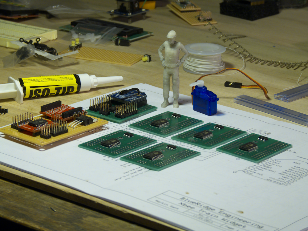
My 3D printed friend looks over a batch of brains going into the oven this afternoon. A completed one is at his feet and below that is the original prototype. For perspective, he’s 6 ft tall in 1:29 scale.
More info: controlwidgets.com
Boards have arrived, here is the first one fresh out of the toaster oven!
More info on these can be found here:
controlwidgets.com
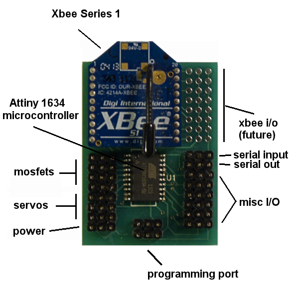
A more informative diagram:
I’m going down much the same road with my new widgets as I did with the Wixels- depending on the software loaded and the application, a Widget can be a client or controller. A client can be a locomotive, turnout or any other device that is controlled via servos or discrete outputs. The controler can be a hand-held interface and/or a computer. In my case this is my Raspberry Pi, configured as a web server/web sockets host.
To that end, I coded up a quick Xbee interface for the Raspberry Pi in python that works with the datagrams in my set of train/control widgets. It’s extremely minimalistic (of course) but allows you to send standard ‘AT’ commands to the Xbee and also send advanced API datapackets. This code assumes that you have an Xbee module configured with X-CTU. I’m using the Parallax Xbee USB board to do this. You will need to set the interface baud rate of the Xbee to 38400 baud and place the Xbee in API mode. Once configured, move the Parallax board to the Raspberry Pi and that’s it. Destination Xbee modules (configured as above) will receive this data (based on it’s destination address of course) and pass this out the serial port to the host. In this case, the host is (will be) my train widget boards. Once they are available that is, perhaps early March (I hope)
Anyhow, you can now control Train Widgets with the following code or adapt it to your own xbee design. XbeeTransmitDataFrame is the primary control interface. All servo, sound and sensor data uses this fixed length datagram. It’s compact and fast and offers 65K of possible command codes (I’ve implemented 3 so far).
xbeeSendDataQuery is used to do a standard ‘AT’ command using the API mode. For example, you can pass ‘M’ and ‘Y’ to this method and it will return the 16 bit node address of the Xbee. Any of the other AT commands can be used as well but you will have to get the data using serial.read() and know where in the packet the return value and how long it is.
xbeeTransmitDataFrame is used to send the 16 byte packets I’ve made up for my implementation. You can see how these are constructed from the C structures below.
import serial

class xbeeController:
    def __init__(self):
        usbPort = '/dev/ttyUSB0'
        self.sp = serial.Serial(usbPort, 38400)

    def xbeeReturnResult(self, datalength):
        return(self.sp.read(datalength))

    def xbeeDataQuery(self, cmdh, cmdl):
        frame = []
        c0 = ord(cmdl)
        c1 = ord(cmdh)
        frame.append(0x7e)	# header
	frame.append(0)	        # our data is always fixed size
	frame.append(4)         # this is all data except header, length and checksum
	frame.append(0x08)      # AT COMMAND - send Query to Xbee module
	frame.append(0x52)	# frame ID for ack- 0 = disable
	frame.append(c1)	# Command high character
	frame.append(c0)	# low character
	frame.append(0)	        # zero checksum location

	cks = 0;
	for i in range(3,7):	# compute checksum
	    cks = cks + frame[i]

	i = (255-cks) & 0x00ff
	frame[7] = i	        # and put it in the message

	for i in range(0,8):	# send it out the serial port to the xbee
            self.sp.write(chr(frame[i]))

    def xbeeTransmitDataFrame(self, dest, data):
        frame = []
        frame.append(0x7e)	# header
	frame.append(0)	        # our data is always fixed size
	frame.append(21)        # this is all data except header, length and checksum
	frame.append(0x01)      # TRANSMIT REQUEST - send Query to Xbee module
	frame.append(0)	        # frame ID for ack- 0 = disable
	frame.append( (dest>>8) & 0x00ff) # Destination address
	frame.append( (dest & 0xff))
        frame.append(0)         # disable ack for fastest transmission

        for i in data:          # move data to transmit buffer
            frame.append(i)
        frame.append(0)         # checksum position

	cks = 0;
	for i in range(3,25):	# compute checksum
	   cks += frame[i]

	i = (255-cks) & 0x00ff
        frame[24] = i

	for i in range(0,25):	# send it out the serial port to the xbee
            self.sp.write(chr(frame[i]))
This is the xbee header information that is in the Widgets. This defines the three control packets I’m sending with the Xbee. These are the 16 bit fixed length packets that ride in the transport area of the above datagram. By keeping them small, I’m getting a 7ms packet transmit time which is very fast.
#define CONTROLLER   0x0000				// XbeeCTRLPacket{}
#define RFIDCOMMAND  0x0010				// XbeeRFIDPacket{}
#define SOUNDCOMMAND 0x0011				// XbeeSOUNDPacket{}

typedef struct
{
	uint16_t destinationAddress;		// Xbee destination address for this client
	uint16_t sourceAddress;				// This node's address
	uint16_t commandID;					// 16 bit command ID
	uint16_t Sound0;					// 16 Bits of Sound Triggers
	uint16_t Sound1;
	uint16_t Sound2;
	uint16_t Sound3;
	uint16_t Sound4;
} XbeeSOUNDPacket;


typedef struct
{
	uint16_t destinationAddress;		// Xbee destination address for this client
	uint16_t sourceAddress;				// This node's address
	uint16_t commandID;					// 16 bit command ID
	uint16_t RFID0;						// 12 bytes of ascii RFID info
	uint16_t RFID1;
	uint16_t RFID2;
	uint16_t RFID3;
	uint16_t misc1;
} XbeeRFIDPacket;

typedef struct
{
	uint16_t destinationAddress;		// Xbee destination address for this client
	uint16_t sourceAddress;				// This node's address
	uint16_t commandID;					// 16 bit command ID
	uint16_t Servo0;					// Servo 0
	uint16_t Servo1;
	uint16_t Servo2;
	uint16_t Discrete;
	uint16_t misc1;
} XbeeCTRLPacket;
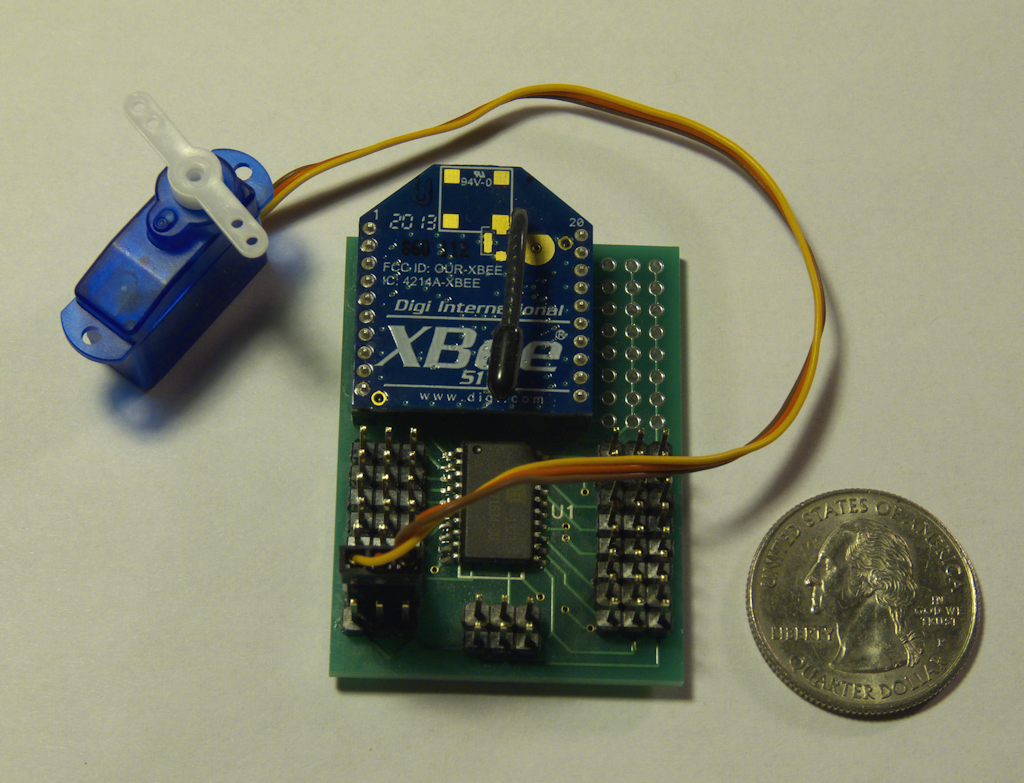
This is the prototype control widget. I originally called them ‘train widgets’ but that is a bit limiting as they should be able to control pretty much any surface vehicle. I wouldn’t use them for flying devices however as the range is only about 300 feet- fine for earthbound machines but a bit too limited for anything that flies.
Nevertheless, since my primary purpose is controlling G scale model trains, this will do nicely. As you can see from the photo, these are very simple devices. An Xbee series 1 and an Atmel Attiny 1634 micro controller. I also have a suite of software modules written to control or monitor each of the functions mentioned in the diagram, plus do all the Xbee network message passing.
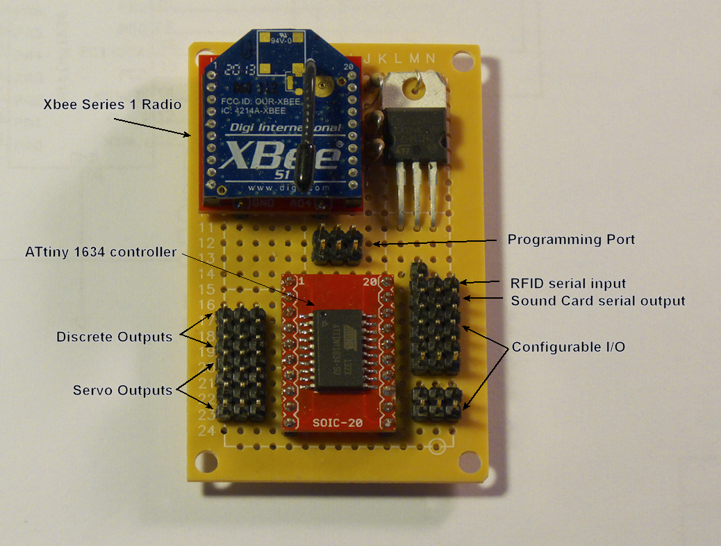
Each widget can control servos, motor controllers, discrete outputs (lights etc), a sound card with 8 channels of up to 1000 sounds, an RFID reader (for position sensing) and a configurable set of I/O pins for inputs (speedometer, current sensor, etc) or SSI/SPI to expand the I/O.
The Xbee allows bi-directional radio communications using the 802.15.4 protocol, so any node can communicate with any other node in real time. One Xbee in a hand-held configuration can control multiple locomotives, turnouts and animatronics, while a computer can also control and/or monitor the same (or other) locomotives or devices.
Anyhow, I’m working on a whole series of designs based on this, I have ordered the first set of PCBs, they should be here in a couple of weeks. After that I’ll be designing PCBs for the handheld, working on the sound card (I have a new one, see this link for more info) and expanding the software modules.
Well, after much debugging and trouble shooting I still cannot get either of my Android Interface prototypes to work. I have tickets open with the support guys but so far they have not been much help. This is rather disappointing but perhaps it’s a good thing. Time to move on. I have all of my control and sound s/w and h/w working, now I need to concentrate putting it into widget form with some custom PCB designs. I have the client widget designed, next are the hand held PCBs which will entail a display board and a keyboard circuit. The computer interface is covered, a parallax Xbee to USB board will be used for that, I just have to get the python drivers together and interface it into my websockets design.
I plan on releasing all of this as a series of several components, or widgets as I like to call them. The first will be the client widget. This will be for installation in a locomotive, turnout or animatronic device. It will interface to servos, motor controllers, my sound board, discrete outputs (ex lights). I will also provide inputs for various things like current sensors and feature an RFID reader port (for position sensing).
The second will be a couple of small PCBs, this will be the hand-held widget. I’ll also offer a resin cast/3D printed housing for this. And like the client widget, the s/w will be open source.
The third widget is the mp3 sound player. This will require the client widget to function.
The last widget will require only s/w as it’s based on the parallax Xbee interface board. You will need one of these anyway to program the Xbees for each of the clients and the hand-held. It will then double as a computer control point for the raspberry pi.
I’ll link all this together with some of the software I’ve done for the Wixels, at least on the HTML5/websockets and server side.
The basic idea is two fold. You can drive your trains with the hand-held and control all client nodes with that (locomotive or whatever) AND/OR control them with the computer or some combination of the two. I’ll open source everything so you have something working right away, yet also have the ability to alter the code to whatever you need. I’ll keep the cost of the PCBs to the absolute minimum and offer them bare, as a kit, or populated and programmed. Stay tuned.
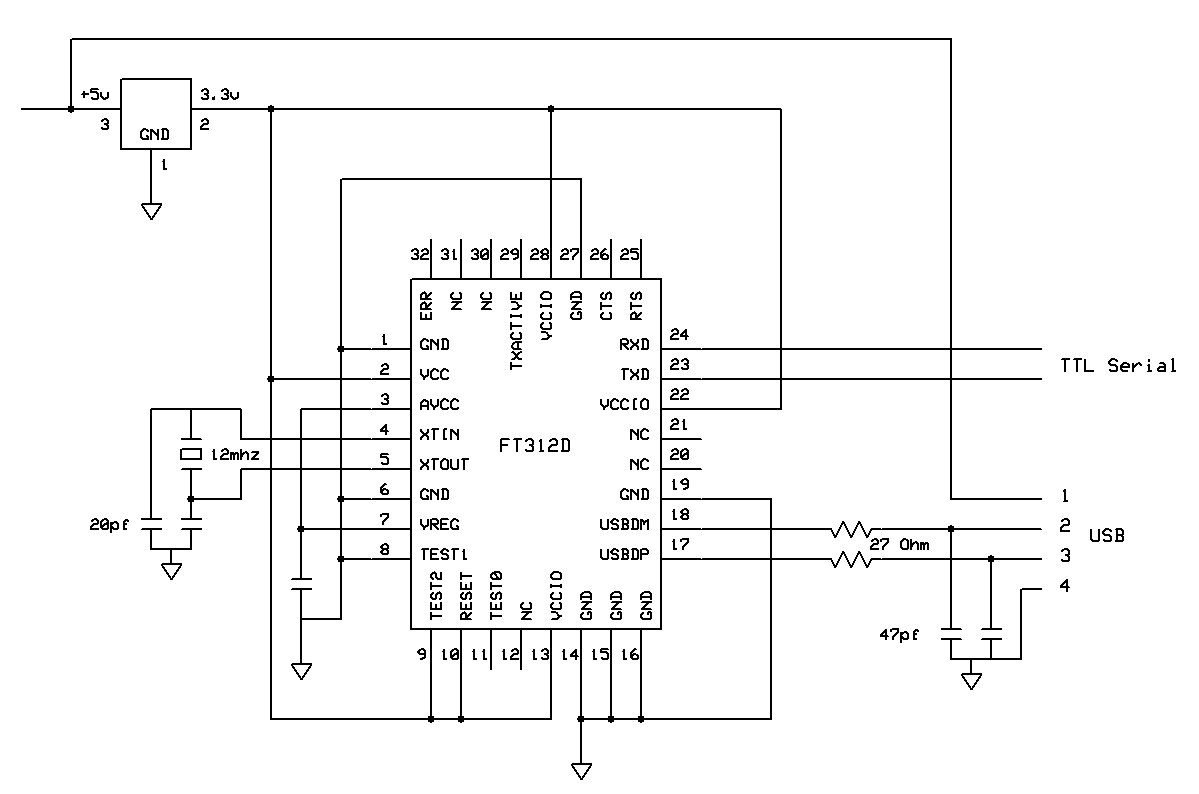
Been a while since my last update. I’m in somewhat unfamilar territory so progress is slow. I’ve been messing around with my Android tablet, the Eclipse IDE for Android and this neat little chip, the FT312D.
In theory, this chip should provide a way to have the tablet control external hardware via ttl serial, and as a bonus, provide external battery power. It acts as a host module and that’s how the tablet sees it but the USB side is somewhat alien to me, both h/w and s/w. My first pass prototype came out a bit sloppy, it connects to the tablet but with less than acceptable results.
So back to the drawing board I guess. Here is a new, base circuit diagram, drawn from the reference circuit on the ftdichip.com web site. I’ve cut out the Attiny, the Joystick and the Xbee for a minimalistic situation. I have all the parts, just have to build it.
I’ll be working with these softwares- Android demo application projects from the chip manufacturer – Android.zip
And of course, to download the Eclipse IDE to load and build all this, you can go here: Android Development
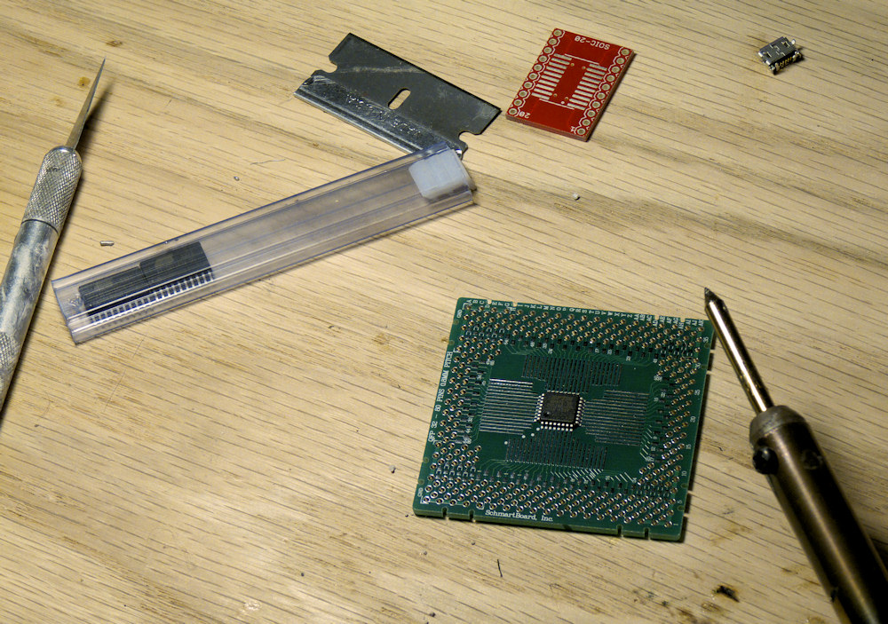
Well, this turned out a lot easier than I thought it would. Align the chip and stick it down with masking tape. Just touch the soldering iron tip to the trace and the chip pin and presto, instant bond, no muss, no fuss. Did the whole chip in just a few minutes.
I’m using a 0.8 pitch Schmart Board to do this, they are a bit pricey but well worth it in terms of ease of use for concocting a breadboard-able SMT chip.
However, it does seem prudent to look into the next step up, surface mount reflow in a toaster oven. This was not bad but these components are getting too tiny to work with and I will need a more ‘small production friendly’ method if I want to sell these things (which I do at some point). Here are a few links I’ve been looking over and does it count I’ve been to Walmart to price new toaster ovens? Ha.
http://www.freetronics.com/surface-mount-soldering-with-a-toaster-oven
http://hackaday.com/toaster-oven-reflow-soldering
Anyhow, to recap, (see below post) this is the interface chip between my control widget- a tiny joystick and xbee radio module- and a cheap android tablet. The idea is to use the tablet as the user interface for the widget as opposed to the controller I have been working on with it’s limited LCD and 16 key interface. (see previous posts) It works ok and it’s cheap but its like really clunky. Time for a fresh morph into a new design.
This turns out to be somewhat more difficult than I realized. To me, this should be a simple procedure. Of course, it’s not so I’ve since found several links that help with just how to do this.
The first is the official Google/Android page which describes their solution for this:
Android Accessory Development Kit
The next is a special chip that takes all of the pain out of interfacing to the Android USB port:
FTDI Android
I’ve since ordered a couple of the chips and assorted hardware including solder paste to do some ‘toaster oven surface mount’ experiments.