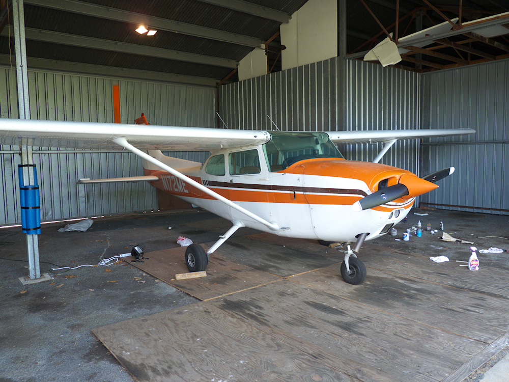
I’ve been neglecting one of my main investments and interests, my airplane- 172ME.
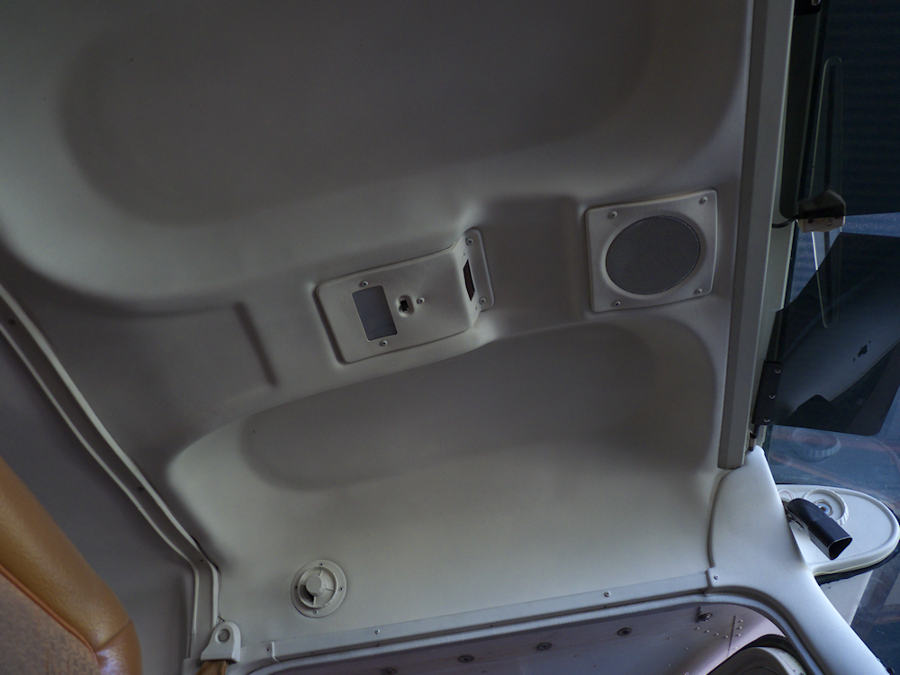
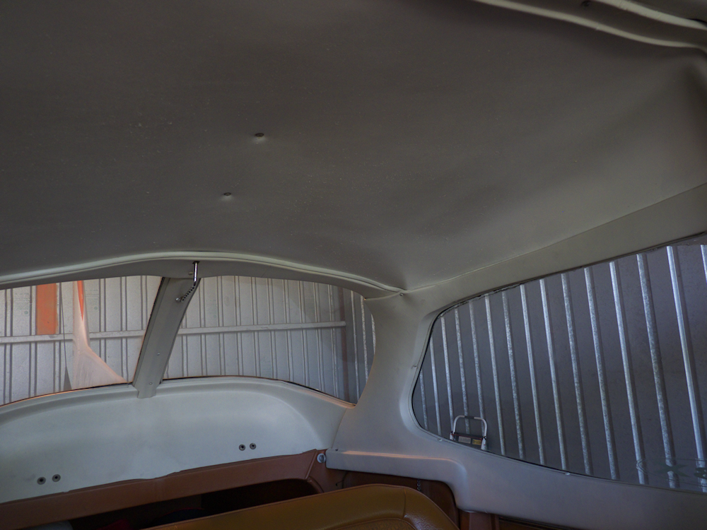
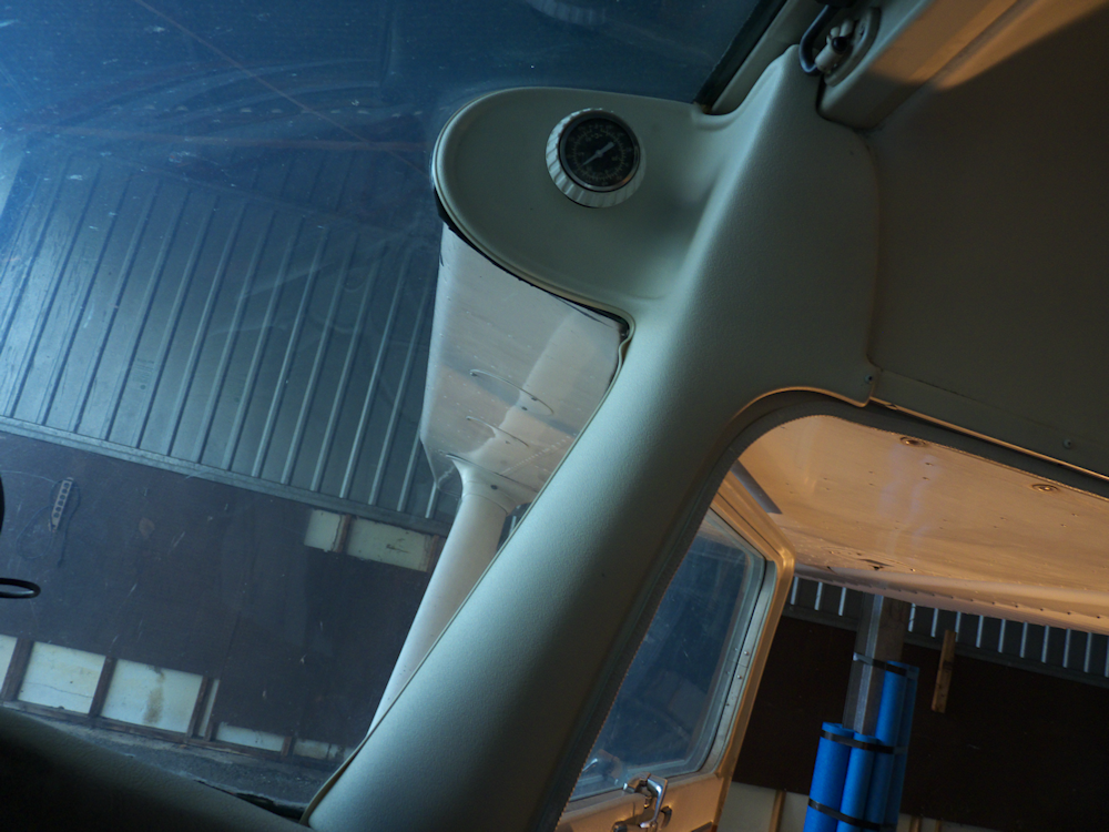
So I spent some vacation time working on sprucing her up. Put in some new plastic trim and painted the headliners. New seats and wall panels are coming in June. I guess next pass will be an owner assisted 100hr with Dan the mechanic man. I need to take out everything to the bare metal on the inside and put it all back in new. And then do something about the paint on the outside. At least touch it up. Needs new seat belts too, and ADS-B. Always something 🙂
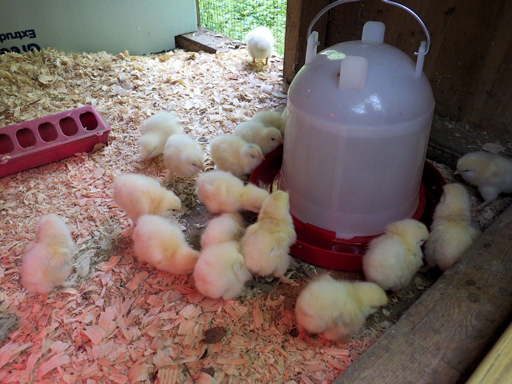
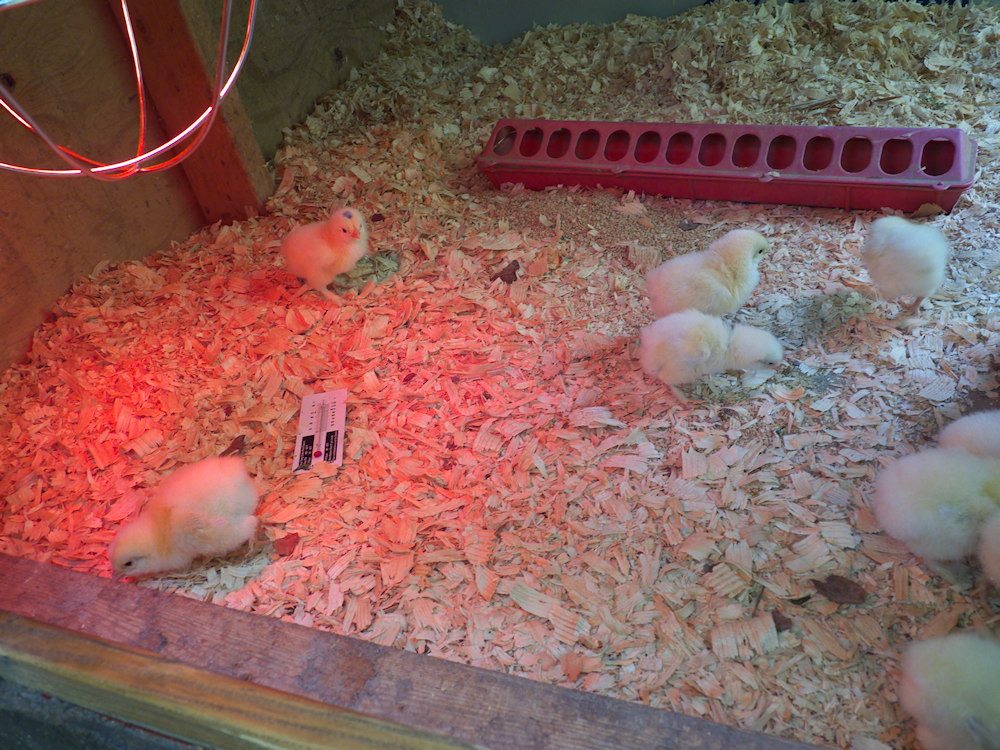
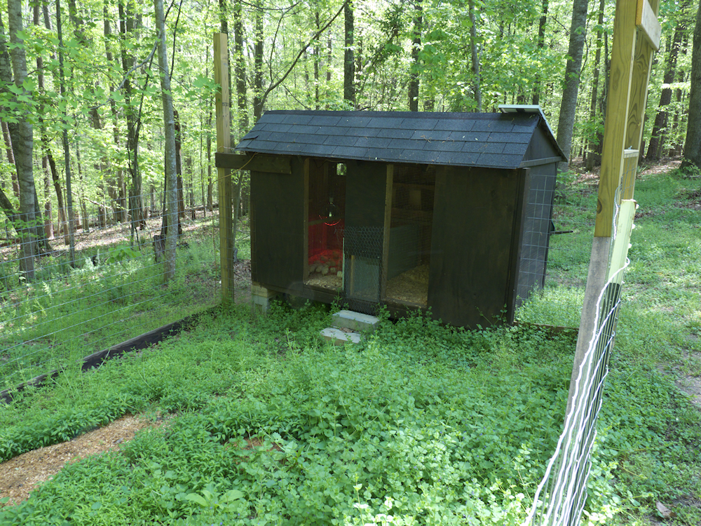
Ok, not engineering but eh. Here are my new Brahma Chickens. Ordered 18, they sent 21. All arrived fine and healthy. These will grow into rather large birds, the males can reach 12-14 lbs. I’m not sure why I like chickens but I do. This is the first time I’ve gotten all one breed of chicken. Last shot IS engineering I guess- my fortress Chicken Coop with automatic aluminum door, all solar powered.
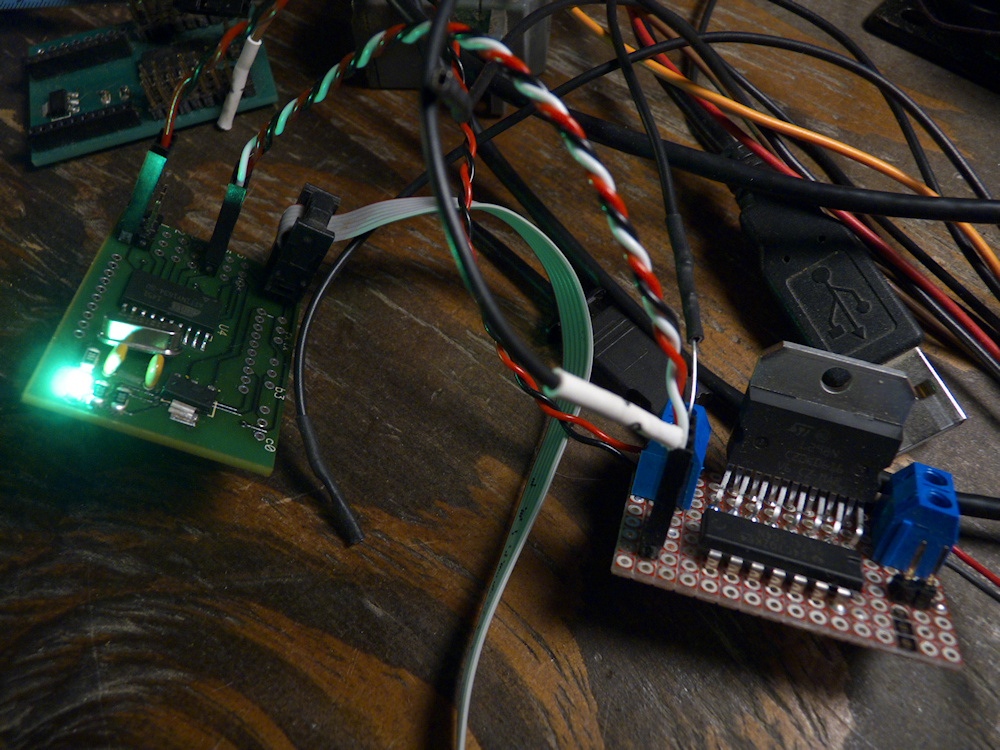
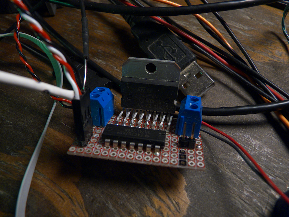
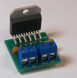
Got my prototype to run first pass. This is a motor driver chip that I have wired to convert logic level DCC to 14v 5A DCC. I was working with the LMD18200 but that sucker was $16 from mouser! Ouch. And it only did 3A. This is the L298N which is only 3 bucks from Sparkfun. Big difference! Now I just need to layout a PCB and get it off this breadboard. Sometimes rainy days are not so bad…
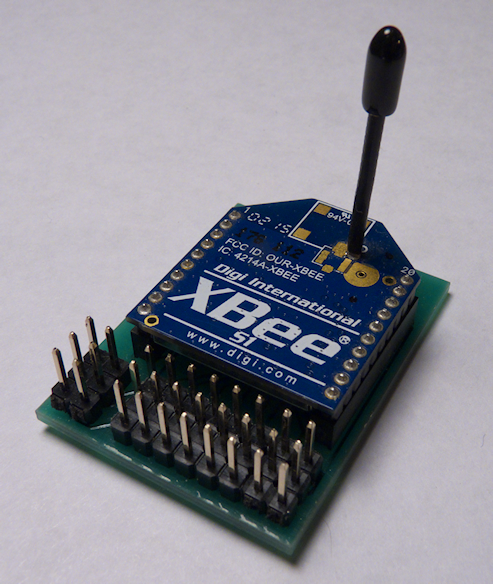
I’ve been working with the series 1 Xbee for several years in order to control large scale model trains. For those not familiar with this device, the Xbee 1 is an integrated package that communicates on the 802.15.4 IEEE wireless network. This is the base level network, only the MAC layer, no mesh or other high level network layers. I have the device configured in ‘API’ mode, which means it accepts standard format messages with a header and checksum and passes those out to the network. It’s actually very simple- all of the nodes are on the network and any node (via a 16 bit address) can talk to any other node. So this means I can do anything with this from controlling trains to controlling turnouts or animations or sending back telemetry from the locomotives, etc, etc.
Well, it turns out that the 802.15.4 protocol is rapidly becoming one of the standards used in IoT, Internet of Things. From what I have read, it has about 65% or so of the wireless IoT market share. So I’ve been working on ways to control large scale trains with this in mind. I’ve had quite a bit of success with this and now one of the outputs of my control widget board can generate DCC messages to directly drive DCC decoders (up to 3Amps for now, I have a 5amp version I’m working on).
This is an open-ended algorithm, it can generate the proper DCC bit stream from any input of hex bytes. This lets me keep the network traffic down as the widget generates all the timing for the DCC signal. I only have to pass the basic commands over the network which keeps everything nice and small and fast.
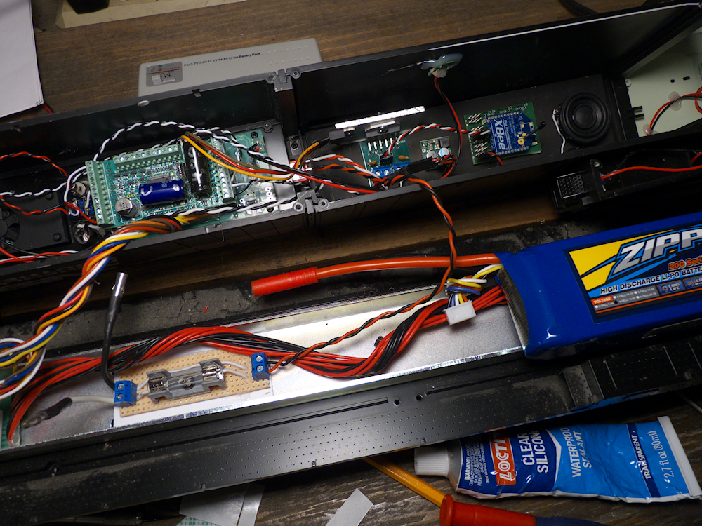
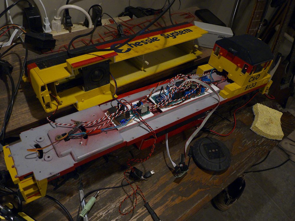
Anyhow, here is the latest incarnation of the DCC 802.15.4 Widget driving a QSI decoder. This one is installed in an Ariso Dash9. Unlike previous designs this one has only one connection- the DCC output from the widget. This is fed to a ‘DCC amplifier’ that then drives the QSI DCC decoder. A 14.8v 5000mah battery provides the power.
This was an interesting install for a couple of reasons. First, the decoder is ‘plug and play’, I disconnected the track pickups and plugged the decoder into the socket- everything just works, no rewire of the motor blocks or LEDs! Very cool. The outputs of the DCC amplifier then drive the decoder directly, no motor controllers or relays or anything.
The second reason was the software. I’m not sure about the vintage of the QSI firmware but it was not happy with the extended DCC packet format for the throttle messages. So I branched the software and made a version that only sends the base DCC packets. I put the QSI into ’28’ step mode and all was good. I wasn’t particularly pleased by this but what can you do eh? I still need to do some CV tweaking for the momentum and braking but it’s working well.
At some point I will be trying out the new WOW large scale decoder and the Economi 400 to see how they react to the extended packets. I’ve played with the Econami 100 and 200 decoders so I assume the 400 will behave in a similar way. Nevertheless, I’m thinking I will need to re-work my firmware to include both the extended and the base level DCC packet generation. That is the official standard according to the DCC docs so I should support it.
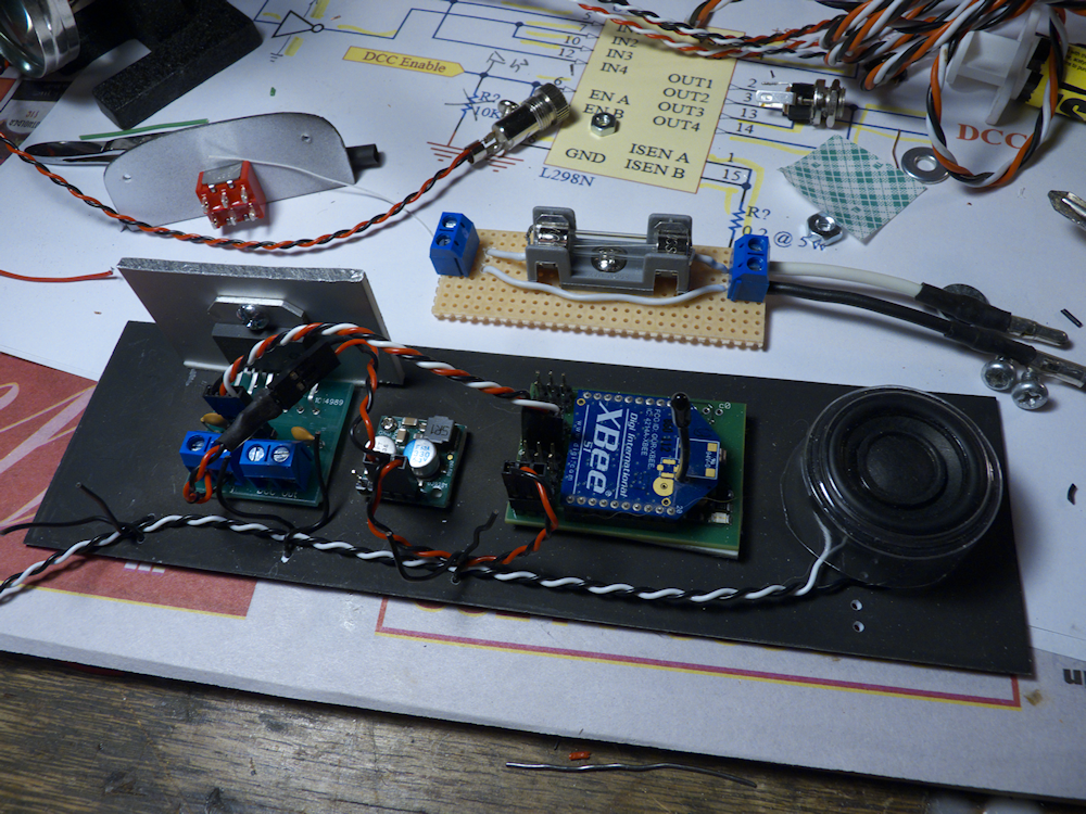
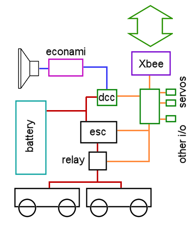
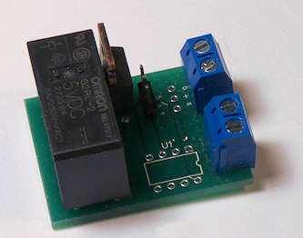
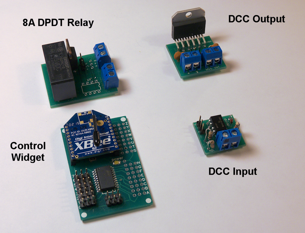
Above is the basic circuit. On the left is the DCC driver, then next assembly is the 14v to 5v stepdown power supply which can deliver 2.5 amps of 5v (for servos, etc) to the IoT Widget. In the middle with the Xbee is (obviously) the Control Widget. On the right is speaker #2, I’ll be routing most of the horn and bell sounds to this one with the big sub in the engine compartment handling all of the prime mover sounds.
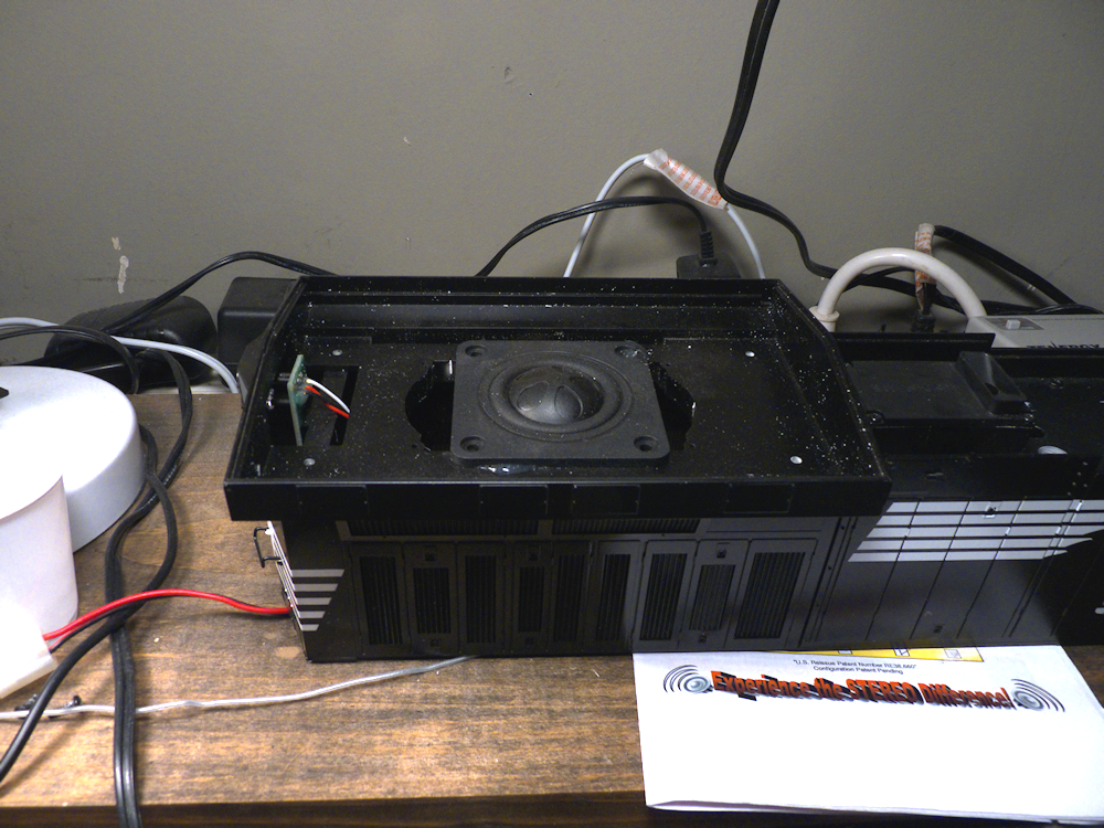
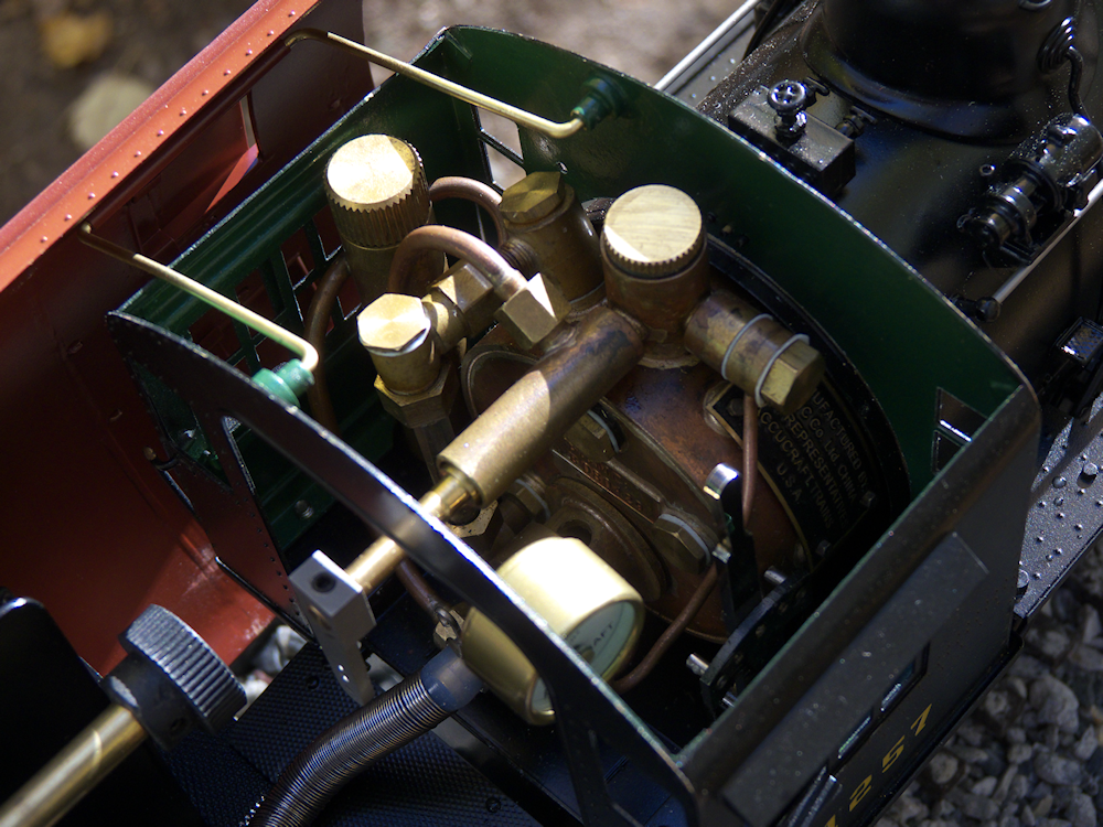
A picture of the main speaker driver. This is a tangbang full range speaker with passive radiator. Really nice bass from this unit. Here is link to it: tang-bang-speaker
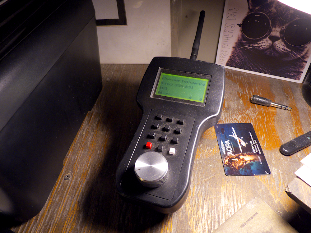
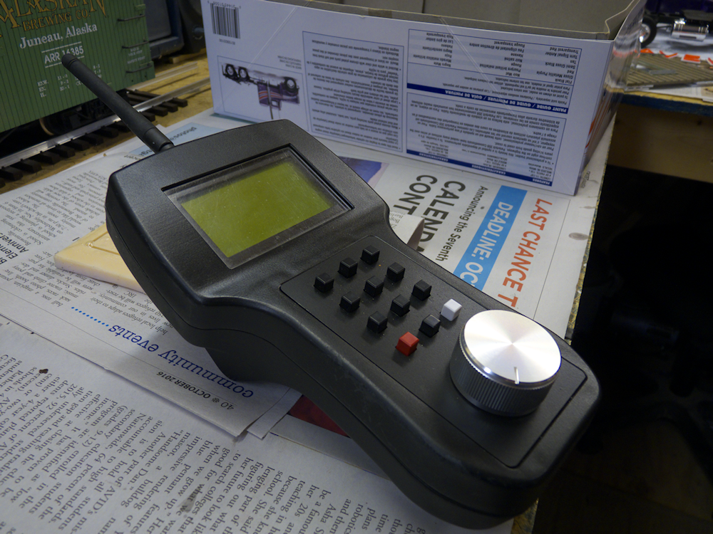
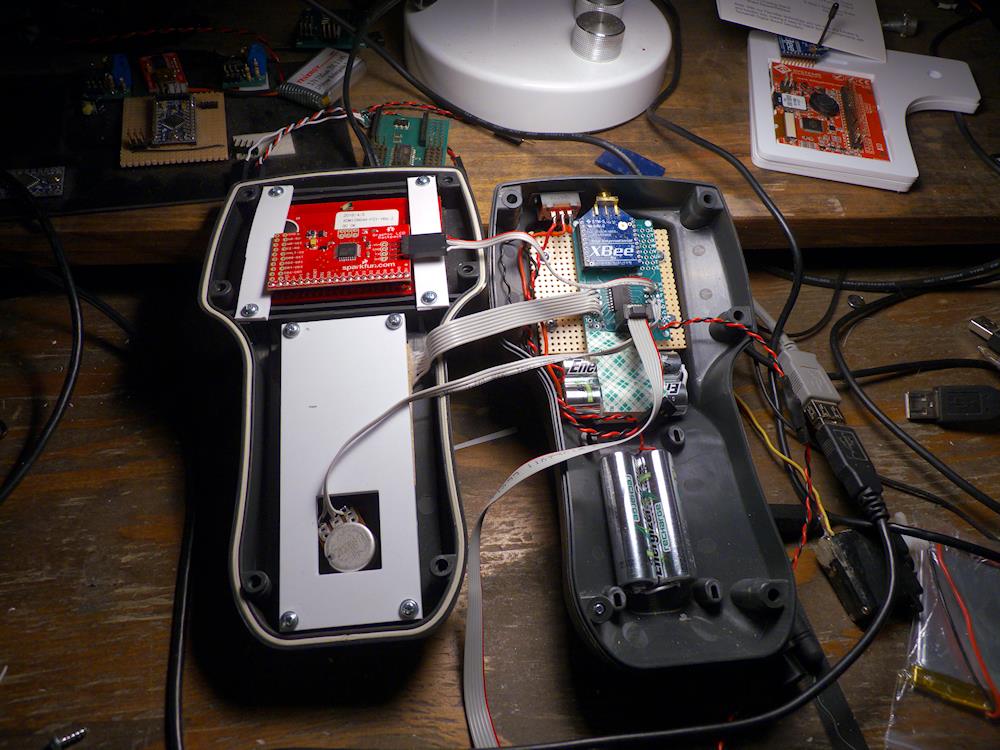
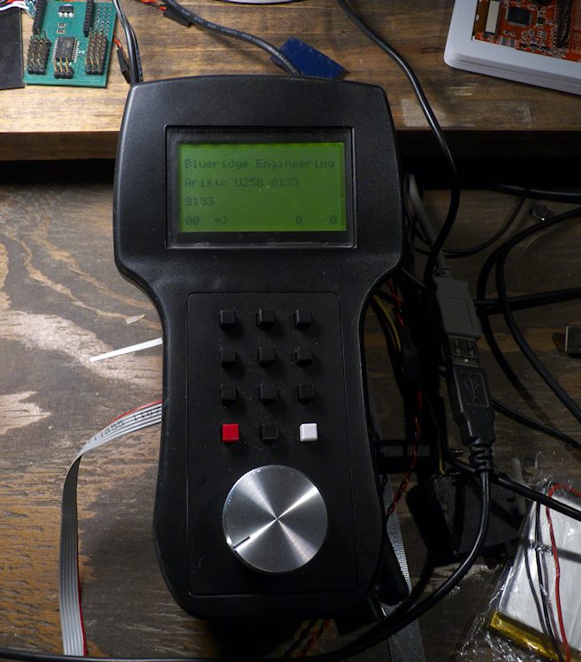
Here is a shot of the ‘terminal’ (Hand held controller) I’ve developed for interacting with the IoT 802.15.4 network. This one is a back-lit alpha numeric display which works great- I can see it out on the layout as it gets dark at night.
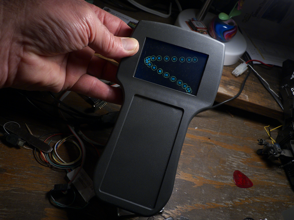
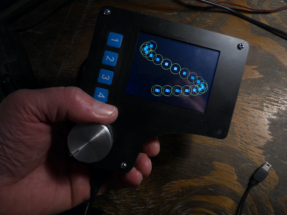
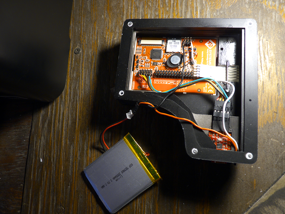
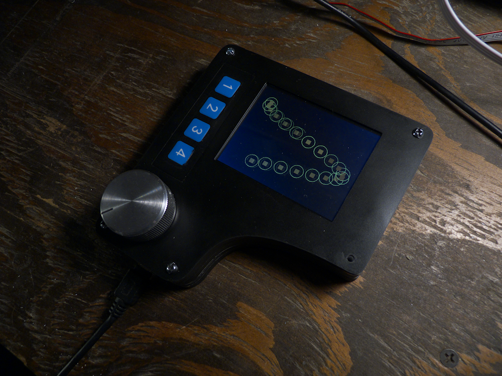
Above is a new design I’m trying out- This is a full color graphic touch screen that has tons of features. It incorporates a usb programmer port, a speaker and a built in lipo charger circuit. I just can squeeze it into the same case as the alpha display so we shall see how it goes. Work in progress.
This is the widget driving an Econami 200. Since it’s only 2 amps, I will probably be using this in a critter or railcar of some type. Right now all I have it hooked to in this video is the speaker.
Here is a video of the widget controlling the QSI. I think all the firmware changes are in so I’ll be buttoning up the unit and taking it out to the layout soon for some real world testing. I may go ahead and run the servo lines out just so I don’t have to open it back up when I put servos on the couplers.
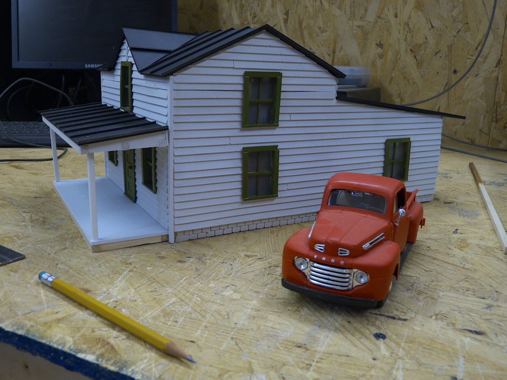
My new Farmhouse. All of the infrastructure was cut out on my 3D router using .060 and .120 sheet styrene. The siding and windows are resin castings. Not quite finished, still needs some details and lighting but it’s almost there.
One thing that I have not been real happy with as I build out my control network, is the hand held controller implementation. I had hoped this design would change that but after I’ve played with it a bit I don’t think so.
It features a uLCD-32 smart touch screen display unit, a large aluminum knob and four tactile hardware buttons. The display unit is a very full featured device including a Lipo battery charging circuit! Very cool. The custom graphics chip and language are very powerful and more importantly FAST. This will take all the UI load off the Xbee/Widget device. More info is here – Serial TFT Color LCD
So, I think I don’t like this one either. I’m going to scavenge the LCD and try to fit it in the case I’ve found for the alpha numeric monochrome unit. It’s a tight fit but the quality of this display is just too good to let it go to waste. I’m finding I like the off the shelf case I have (I bought two) better than I thought. I have somewhat large hands so I can hold it in my left and turn the knob with my thumb.
So this one is defunct now. More to come on this project later.
I’ve been working on this Xbee DCC thing for quite some time now and have finally finished it off. Or more like, I’ve finally gotten to the point where I think I could ‘release’ the code and the hardware. I have created a version 2.0 release branch for the code and have most of the hardware in a PCB state so it’s getting pretty mature. And more importantly, it works pretty darn good now!
The basic problem I’m trying to solve is how to control my trains, both electric and live steam, with one network. This network would also control pretty much everything else- turnouts, lights in buildings, signals, whatever. Everything on the network- trains, towns, turnouts, signals, would be capable of talking to everyone else, in real time. This would then allow you to tap into the network with a standard interface to leverage whatever application you want on top of it.
This is the reason I went with the Xbee. Unlike simple R/C or even Bluetooth, the Xbee (and I am speaking specifically about the Series 1 Xbee, NOT the Pro Zigbee) is a low level point to multi-point network. It runs at 250Kbps and has a range outside of about 100 meters or 300 feet. Every node on the network has a 16 bit address and can talk or respond to any other node.
One thing that took quite a bit of time to develop and test was the DCC output. The widget generates 128 step DCC throttle messages and DCC Function Messages F0-F12. It’s a bit basic, you have to program your DCC decoder with an external DCC unit and (for now anyhow) you only get those specific DCC transaction but as you can see from the video, that gives you lights, sounds and throttle.
I also completely redesigned the Master side code as well. It’s now far more generic in terms of messages. So I designed a new hand-held controller for it to reside in:
Hand Held Controller 2.0
Here is a basic diagram of what is going on in the U25B in the video. These are the components and control and power flows. Red is power, orange is logic, blue is DCC. Also, it’s not on the diagram, but the economi is controlling the lights and the Widget is driving 2 servos to automate each coupler. The ‘other I/O’ is also hooked up, a current sensor monitors the amps flowing to the trucks and there is also a photo detector that gives a pulse on every wheel revolution (for speed and distance). (The software is not currently looking at these however)
Basic Control Diagram
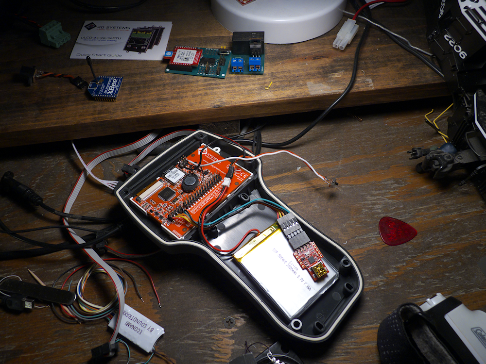
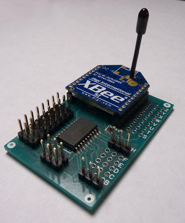
All of the components in the client are now on PCBs, no more proto or perf boards:
A couple of pictures of my latest iteration of wireless DCC and train control. This one has been refactored a couple of times and I now have a nice compact executable that takes throttle and function commands from any controller (in this case, my new hand held design) and converts them to both servo pulses (for the motor controller) and DCC output commands to control the lights and sounds. The speaker is a 2 inch full range with a passive radiator, sounds nice and full. The lights are all surface mount LEDs driven by CL2Ns. I also have servos on the couplers, they are tied to the F6 and F7 functions on the handheld.
Here are the basic components that go into the locomotive:
Everything is now driven by a simple command structure- throttle commands and function commands. The throttle controls the servo 0 spot, I’m using a 20A ESC to drive the motors in the U25B. The throttle commands are also used to drive the DCC decoder for the engine sounds. Since this is an HO Economi decoder, it doesn’t have the current output directly. But it does have great sound and I also drive the lights with it.
Why Xbee everyone asks? Because this is true networking. Everyone is on the same network and can speak or be spoken too. True point to multipoint. This opens up all sorts of possibilities for automation, signals, detection blocks and computer control. Something Bluetooth cant’ do. It’s also ‘industrial strength’ in that Digi has been making Xbee modules for many years now. They are FCC approved out of the box and