I’ve been working on this Xbee DCC thing for quite some time now and have finally finished it off. Or more like, I’ve finally gotten to the point where I think I could ‘release’ the code and the hardware. I have created a version 2.0 release branch for the code and have most of the hardware in a PCB state so it’s getting pretty mature. And more importantly, it works pretty darn good now!
The basic problem I’m trying to solve is how to control my trains, both electric and live steam, with one network. This network would also control pretty much everything else- turnouts, lights in buildings, signals, whatever. Everything on the network- trains, towns, turnouts, signals, would be capable of talking to everyone else, in real time. This would then allow you to tap into the network with a standard interface to leverage whatever application you want on top of it.
This is the reason I went with the Xbee. Unlike simple R/C or even Bluetooth, the Xbee (and I am speaking specifically about the Series 1 Xbee, NOT the Pro Zigbee) is a low level point to multi-point network. It runs at 250Kbps and has a range outside of about 100 meters or 300 feet. Every node on the network has a 16 bit address and can talk or respond to any other node.
One thing that took quite a bit of time to develop and test was the DCC output. The widget generates 128 step DCC throttle messages and DCC Function Messages F0-F12. It’s a bit basic, you have to program your DCC decoder with an external DCC unit and (for now anyhow) you only get those specific DCC transaction but as you can see from the video, that gives you lights, sounds and throttle.
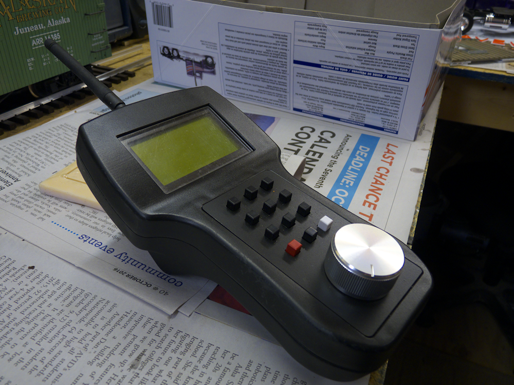
I also completely redesigned the Master side code as well. It’s now far more generic in terms of messages. So I designed a new hand-held controller for it to reside in:
Hand Held Controller 2.0
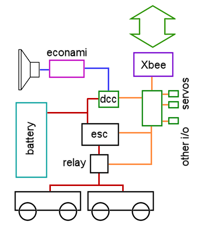
Here is a basic diagram of what is going on in the U25B in the video. These are the components and control and power flows. Red is power, orange is logic, blue is DCC. Also, it’s not on the diagram, but the economi is controlling the lights and the Widget is driving 2 servos to automate each coupler. The ‘other I/O’ is also hooked up, a current sensor monitors the amps flowing to the trucks and there is also a photo detector that gives a pulse on every wheel revolution (for speed and distance). (The software is not currently looking at these however)
Basic Control Diagram
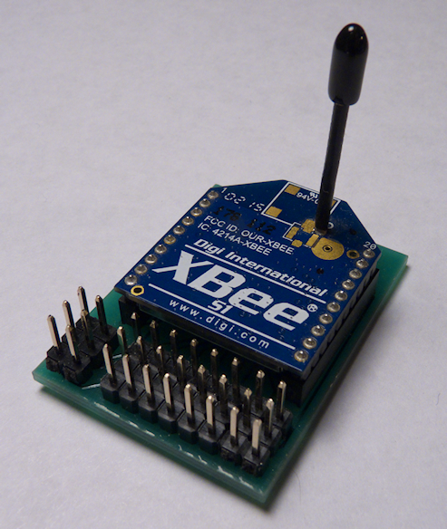
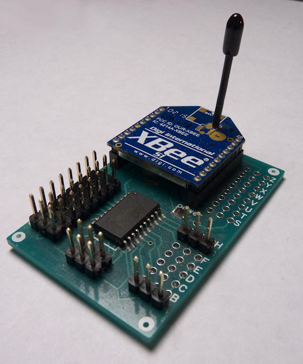
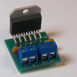
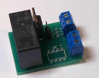
All of the components in the client are now on PCBs, no more proto or perf boards:
