Other Stuff

Been a while since my last update. I’m in somewhat unfamilar territory so progress is slow. I’ve been messing around with my Android tablet, the Eclipse IDE for Android and this neat little chip, the FT312D.

In theory, this chip should provide a way to have the tablet control external hardware via ttl serial, and as a bonus, provide external battery power. It acts as a host module and that’s how the tablet sees it but the USB side is somewhat alien to me, both h/w and s/w. My first pass prototype came out a bit sloppy, it connects to the tablet but with less than acceptable results.

So back to the drawing board I guess. Here is a new, base circuit diagram, drawn from the reference circuit on the ftdichip.com web site. I’ve cut out the Attiny, the Joystick and the Xbee for a minimalistic situation. I have all the parts, just have to build it.

USB-Android-FT312D

I’ll be working with these softwares- Android demo application projects from the chip manufacturer – Android.zip

And of course, to download the Eclipse IDE to load and build all this, you can go here: Android Development

tinyparts

Well, this turned out a lot easier than I thought it would. Align the chip and stick it down with masking tape. Just touch the soldering iron tip to the trace and the chip pin and presto, instant bond, no muss, no fuss. Did the whole chip in just a few minutes.

I’m using a 0.8 pitch Schmart Board to do this, they are a bit pricey but well worth it in terms of ease of use for concocting a breadboard-able SMT chip.

However, it does seem prudent to look into the next step up, surface mount reflow in a toaster oven. This was not bad but these components are getting too tiny to work with and I will need a more ‘small production friendly’ method if I want to sell these things (which I do at some point). Here are a few links I’ve been looking over and does it count I’ve been to Walmart to price new toaster ovens? Ha.

Suface Mount Soldering Tools

http://www.freetronics.com/surface-mount-soldering-with-a-toaster-oven

http://hackaday.com/toaster-oven-reflow-soldering

Anyhow, to recap, (see below post) this is the interface chip between my control widget- a tiny joystick and xbee radio module- and a cheap android tablet. The idea is to use the tablet as the user interface for the widget as opposed to the controller I have been working on with it’s limited LCD and 16 key interface. (see previous posts) It works ok and it’s cheap but its like really clunky. Time for a fresh morph into a new design.

This turns out to be somewhat more difficult than I realized. To me, this should be a simple procedure. Of course, it’s not so I’ve since found several links that help with just how to do this.

The first is the official Google/Android page which describes their solution for this:
Android Accessory Development Kit

The next is a special chip that takes all of the pain out of interfacing to the Android USB port:
FTDI Android

I’ve since ordered a couple of the chips and assorted hardware including solder paste to do some ‘toaster oven surface mount’ experiments.

As we enter 2014, I thought I would post up a recap of what I’m working on. Primarily I’m developing a wireless method for controlling moving vehicles. In my particular case, this is Garden Scale (G) model train locomotives. However the principles and widgets I’m designing could be used to drive almost anything via real time wireless up to a distance of about 300 ft (100 meters).

The key difference between my method and say standard FHSS (or similar) 2.4Ghz Radio Control is that I am oriented toward a computer driven network, in my case, 802.15.4 as implemented with the Xbee Series 1 modules.

Why a computer network? Well, for one, it gives me fine control over the exact data I’m passing back and forth. Second, it’s bi-directional. The network is oriented as a single to many so any device can talk to any other device. Each Xbee module has a unique 16 bit ‘node address’. You just form a message, add the address of the node you want it to go to and send. The network takes care of getting it there.

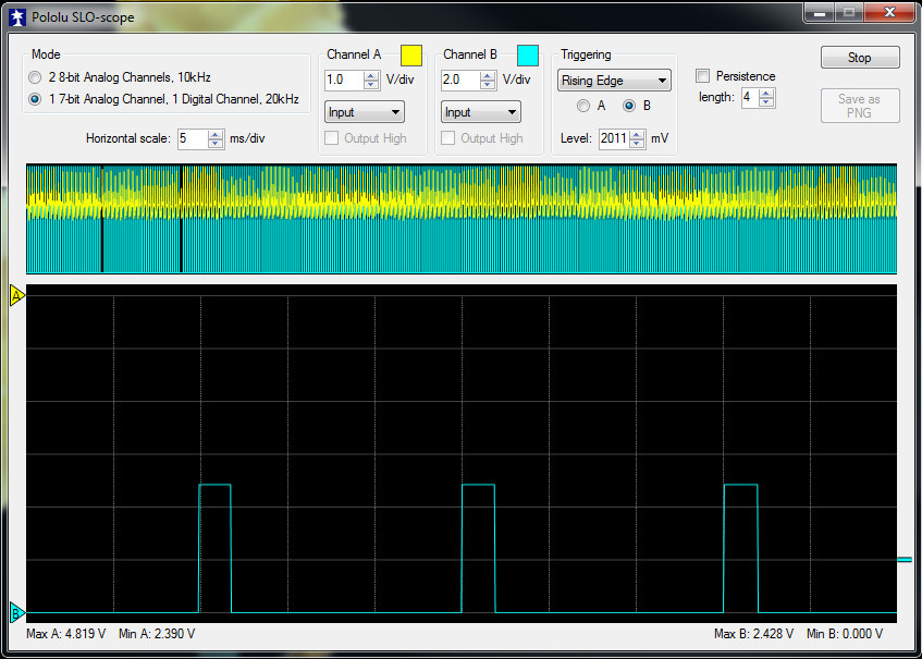
This is quite powerful. You can be sending control data to your locomotive and then, as it passes over an RFID tag, it could send that position data back to the computer (or your hand-held, or another device, etc) in real time. Additionally, other data such as speed, current draw, etc could be returned from the locomotive as well. Just because this is a computer type network, it isn’t slow. I’m getting data packet transmission times in the 7ms range which is quite fast. (For reference, your average servo scan time is 20ms)

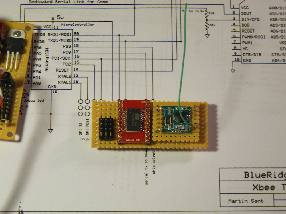
Anyhow this level of potential automation is, by electronic design standards, fairly simple. I have an Xbee and an Attiny 1634 Microcontroller as the main components of my ‘Train Widget’ and that’s pretty much it. Basically about $22 worth of electronics as the ‘brain’ of all of my devices.

mainWidget

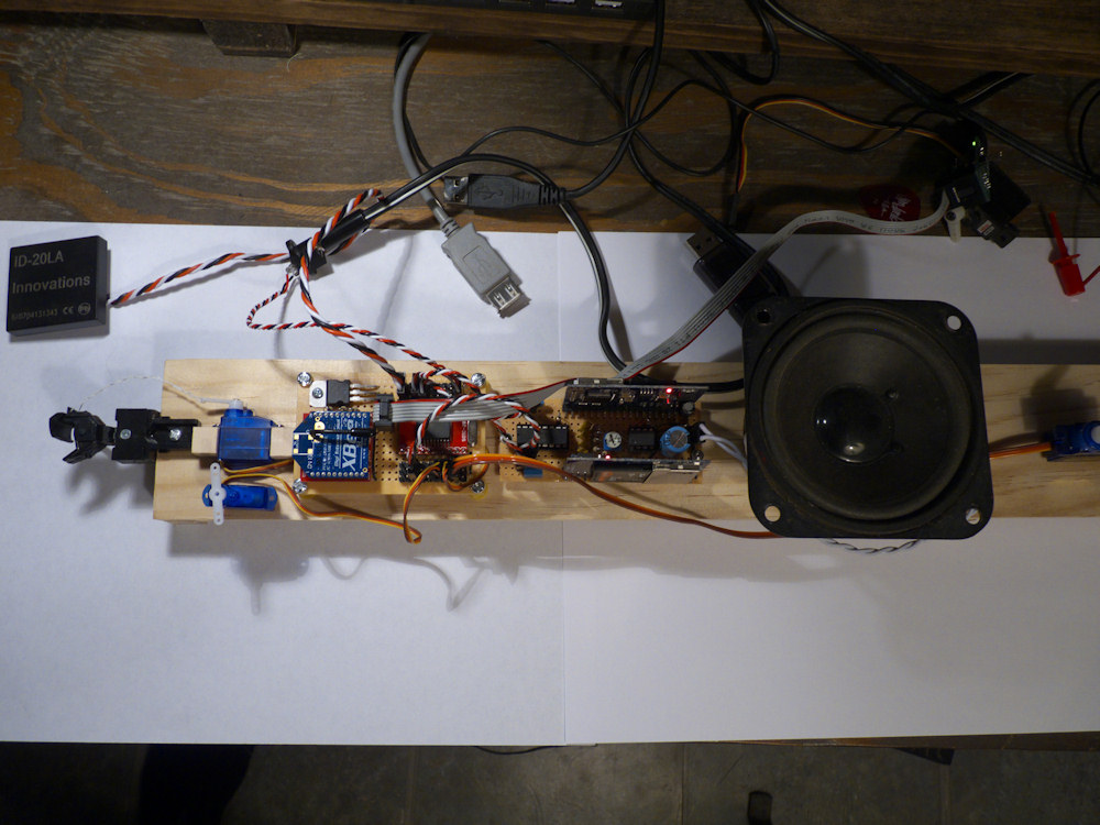
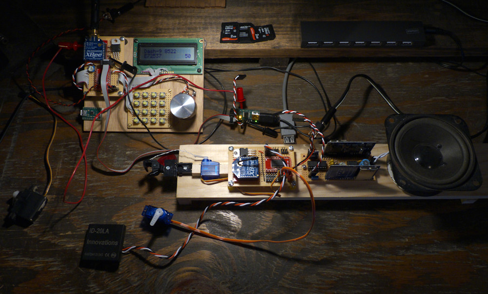
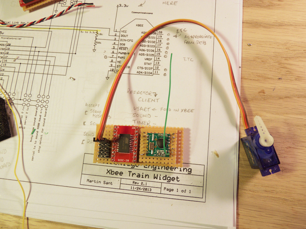
This is a picture of the basic train widget. Xbee does the communications, the Attiny handles the processing and drives the servos and motor controller. It also sequences the mp3 players (2 stereo channels) so you can play sounds via commands sent over the network or by throttle control positions. The two cards are just to the left of the speaker which I’m driving with a generic LM386 amplifier chip and some caps from Radio Shack.

widgetDetail

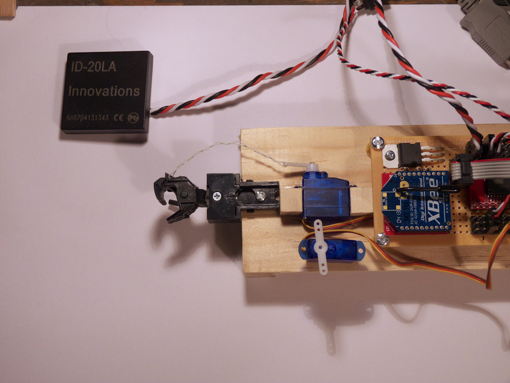
Above is a shot of the front end showing the coupler connected to a micro servo, the ‘back’ coupler servo sitting beside it and the RFID reader in the upper left. I have all of this working including the transmission of the RFID data to the hand-held.

handheldA

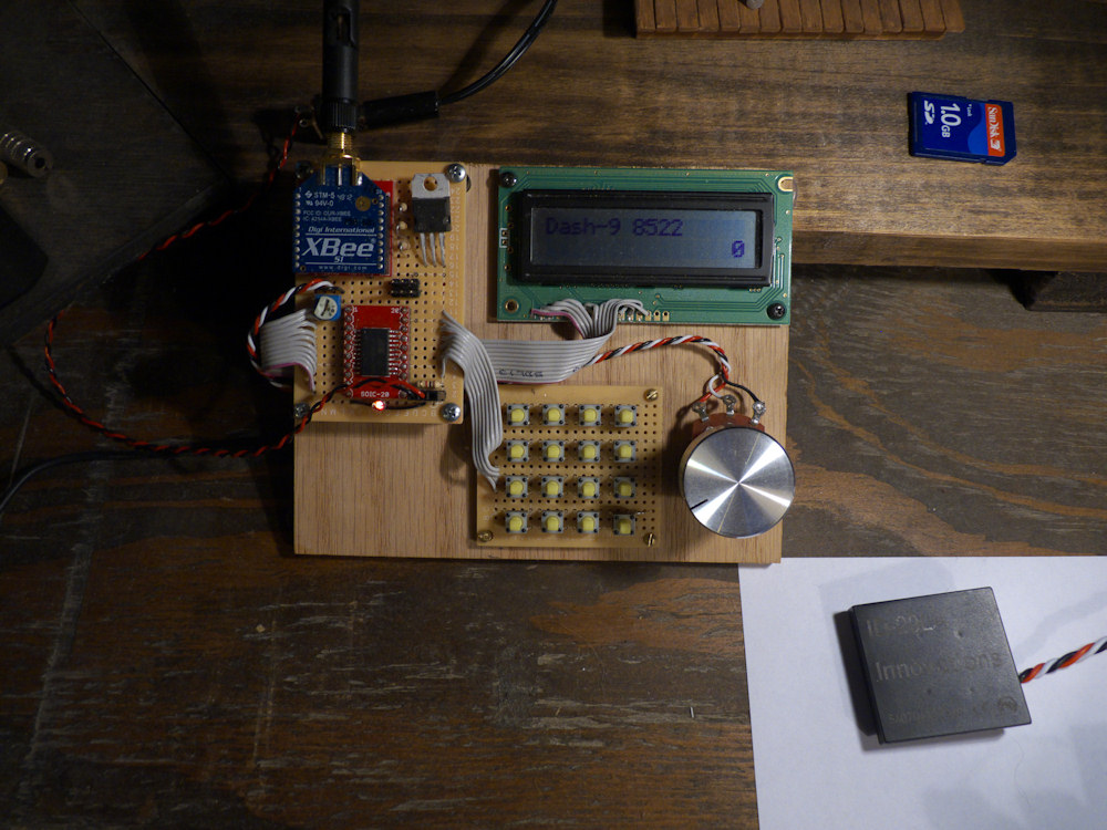
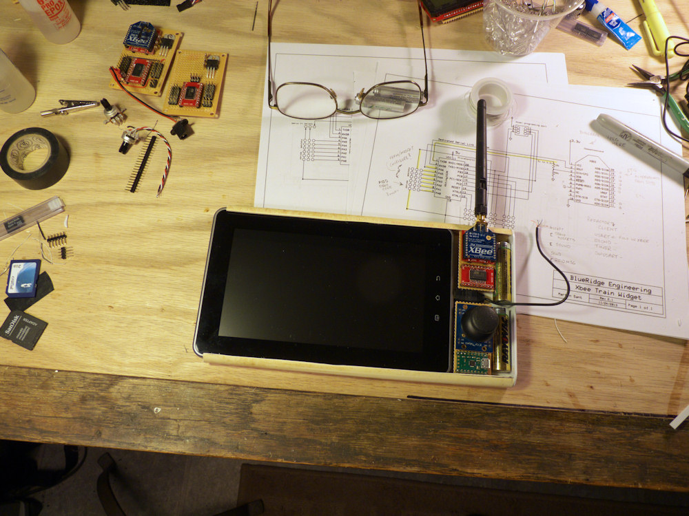
This is a picture of my stand alone ‘simple’ hand held throttle prototype. I also have all of this working, however only at a basic level of controlling one locomotive at a time, I don’t have any multiple unit code in there yet. I’m also thinking of going with a graphic display instead of this ASCII only one and also designing a ‘cradle’ or appliance of some sort so I can use my tablet as a user interface instead of a LCD. (See the post below this one)

couplerRF

Finally, this is a pic of my uncoupler device. One of these per car with the locomotive in charge of each one. The handheld would allow you to address the locomotive and then each car individually to uncouple anywhere. Each of these consist of one Attiny Microcontroller and a small 2.4Ghz transceiver. The locomotive has the ‘master’ transceiver and can talk to each car in the train that has a ‘slave’. The Attiny then controls the servo motor to move the coupler. This is clocking in at about $2 for the Attiny and $8 for the transceiver. Add $4 for a servo. Not super cheap but not too bad. $18 per car? I guess. Hmm, need batteries too…

xbeeTX

Phase B of a hand held transmitter takes shape. This is a rough approximation but I think it will serve as a master for an RTV mold to cast a resin model from. It still needs a bit of design work but this is the basic idea. Xbee transmitter, 1634 Attiny, Parallax Joystick and a Pololu USB/serial interface plugged into the tablets’ USB port. I had considered Bluetooth but it’s the first thing to get dropped on cheap tablets, whereas everyone has USB.

Originally, I had something similar that I had put standard R/C radio guts into, however there was no actual interface to the tablet except via wifi. This design, although in the early stages, will interface with the tablet for a user interface, plus transmit directly on the Xbee Network. The tablet will also do standard WiFi so I can interface to the server as well. With an additional Xbee node on the server, (which will be a Raspberry Pi), all sorts of control possibilities emerge, just requiring s/w. I’ve downloaded the Eclipse SDK for Android as well, I have limited app development experience, at least in the native Java, but it seems like an interesting challenge. I have done some Python development on Android and may end up doing that here too, not sure quite yet. What I would like is to run Chrome on this tablet as they have a serial port API. However, despite this being an Android tablet, I can’t get Chrome to install. Go figure.

After more testing, it seems there is no real need for the 18.432Mhz crystals. Since they cost money (a buck) and require two pins, I’ve decided they are not worth the trouble so I’ll be disabling them on my test widgets. In the meantime, I’ve tweaked the s/w uart (which is how this all started) and made it work really solid using the standard on chip clock. If you would like the source, it’s adapted from a project I got off of AVRFreaks. This only offers transmit, no receive, I use it primarily for driving two mp3 sound cards but it’s also useful for debugging. You can find the source here:

Attiny Software UART Source Code

xtal

I’ve retrofitted one widget and am building another from scratch, both have 18.432Mhz crystals driving the clock instead of the internal resonator for some experimentation and prototyping. Adding a crystal takes two pins but what can you do eh?

I have one running and so far and everything seems a bit tighter, but not dead nuts on like I was looking for. Note the couple of nanoseconds off on the first pulse. Main servo cycle is also 15ms instead of 20ms. Not sure I like that.

I think I’m missing something in the algorithm aspect of the servo drivers so I may refactor it for the third time. The above is a hack, I’m not fond of it but it works.

The big revelation here is that the timers must have some intrinsic slop which you have to compensate for. I found this while fixing the s/w uart so perhaps some servo driver adjustments are prudent.

Speaking of, the s/w serial out is now dead on, I get zero errors out at 4800 baud. So now I have one dedicated h/w serial link to the Xbee, a dedicated h/w serial RX from the RFID reader and a s/w tx to the sound boards. Sweet.

Well, after much poking about, taking scope traces and trying various prototype code, I’ve come to the conclusion that a s/w driven uart to control the sound boards is just not going to work reliably. I’m not sure why, but the timers on the Attiny 1634 seem to be off a bit sometimes. Quite often actually. I noticed some of this on the servo control code, but the servos are more forgiving so they don’t mind much and work fine. At even 4800 baud though, the bits are off by enough to cause the wrong data to be clocked into the sound card- Yuck.

I can use one of the onboard h/w uarts and it’s rock steady but I really didn’t want to do that. One of the h/w uarts is dedicated to the Xbee and the other I use for the RFID reader. It’s a shame the RFID reader wants to run at 9600 and the sound boards wants 4800, otherwise I would be set. However I don’t think there is a way to change either of them so I’m kinda stuck.

Anyhow, I’m guessing it’s because I’m running the chip on the internal clock, so perhaps an external crystal is the ticket. I have a couple of 20mhz xtals around but it looks like the best ‘baud’ friendly crystal is 18.432 which gives 0% error on all the rates. They are a buck from mouser but will consume two pins on the chip. Oh well.

Looks like the best bet is to do a 3.0 design with the crystal and then move all the I/O off to the SPI interface, that way I can control 32 bits of I/O for about $3. This lets me control the sound plus the 915mhz radio for the automatic uncouplers too. Hmm.

P1030763

I refactored the software for both the master and client nodes over the last few days. I cleaned up some of the prototype code, added some basic structures to lay over the xbee transmit packets and moved things around just a bit. As far as functionality, I can now control three servos and send the RFID tag reading back to the master. If you look closely at the display you can see the raw hex code from a read in the lower left of the display. The ID20 from Sparkfun is a really nice reader, it catches the card passing by very quickly at about 40-50mm.

This also shows some experiments with the Kadee coupler controlled by a servo. Seems to work well, but this is on a bench test setup, not a real locomotive- but I’m optimistic. All I did was drill a very small hole in the ‘tab’ on the coupler. This is a standard Kadee 787 coupler meant for the Aristocraft RS-3. The actuator wire will be replaced by a chain or something more cosmetically pleasing.

The sound cards are the next step. Right now I’m feeding the power from the same bus as the servos so I get a bit of noise mixed into the amp output. I’ll clean that up later, for now all I hear is the servo when it moves, other than that it sounds fine, good enough to get the s/w working.

P1030760

I’m thinking of how to make the Kadee couplers automatic per car. It’s easy to add them to a locomotive, I’ve allocated two servo controls to my XBee wireless widget controller for that. The tougher part is how to make something that will do individual cars.

Here is what I’ve come up with. It clocks in at about $15 in electronics. Two sub-micro servos for $3, an attiny 1634 at $2 and a WRL-12031 wireless transceiver for $7. That’s $15 per car. Hmm. Still a bit on the high side but if you could have the locomotive be the master and then control each coupler on each car in the consist, you could do some nifty automated switching moves, eh?