Archives

All posts by admin

1ChannelSound

I realized I didn’t have this posted up- this is the single channel mp3 sound card from mdfly.com combined with a simple audio amp. The amp is quite loud and can be built with parts from Radio Shack. This is what I’m using on my RS3 in the pictures below. I’m using the Attiny 1634 s/w UART to drive this from the client widget. It works quite well, you just send a single byte to the card to set the volume or play one of the sounds. However, you get what you pay for, $10 only gets you one sound at a time.

P1040103

P1040101

P1040102

Here are a couple of shots of my control system going into my Aristocraft RS3. The power is all in the back end, I have a 5000mah 14.8v lipo pack driving this beast with a Pololu 18v7 motor controller powering the trucks. A very potent drive train. Anyhow, these pics show the brains- the Atmel 1634 board, the Xbee Series 1 and the MDFly mp3 sound card. Not seen is the RFID reader on the fuel tank- I’ll post that up later. Phew, some work and lots of engineering spits and fails but it’s now pretty clean and works well. I did downsize the controls a bit, I’m only driving the motor, the two coupler servos and the sound card. I left the lights on a manual switch and there is a current sensor in there but I’m not looking at it right now. As mentioned, the RFID is also connected and works so I do have the basics of a computer controlled system. The main control boards are also reasonably accessable by taking off just the short hood of the locomotive so tweaking the firmware, sounds and the pololu motor controller won’t require the entire locomotive to be taken apart (which is a BITCH to say the least!)

RS3Finished

Finally have all of the connections wired and (more or less) tested. I’ve added LEDs to the running lights and servos (not shown) to control the couplers. Just need to add about 11oz or so to the fuel tank and put it all back together for final testing. I’ve attached a programming cable to the microcontroller board so I can download new builds or tweak the s/w if required. Phew. This has been quite a bit of development. The control widget itself went through many interations (see controlwidgets.com) as did the power board. I’ve settled on the Pololu 18v7 programmed to only give forward motion with a relay switching between forward and backward. Anyhow, soon we will be doing some real world testing.

This is a quick project I’ve been working on to test the feasibility of using wifi to directly control something.

It uses a slider on an android app to control the position of a servo in real time using my widget and the Sparkfun WiFly Module.

pygame

There are three parts, the hardware, which is the widget and the Wifly module, the microcode that goes into the widget and the app code on the tablet.

(This is a rather lengthy post so I’ve moved this to a page of it’s own)

You can find it here- Simple Wifi Servo control with Android

As far as conclusions from this, I don’t particularly care for 802.11 for control. In my case, the primary objection is well, it’s not really meant for that sort of thing and I don’t like all the complicated message transactions this entails. Your mileage may vary on that. The other thing is my cheap tablet doesn’t have a very good wifi range so at 30 ft or so I start to loose control. Granted, much of this could probably be resolved with an improved algorithm on the app side, or perhaps a better device (I’ve resisted getting a smart phone). But for me, I prefer the Xbee series mentioned elsewhere on this blog so I will be sticking with that project before I come back and put any more effort in this one.

basestation

This will be my ‘bridge’ between standard wifi and the Xbee network. That is a Raspberry Pi attached to the top, configured as an Apache web server. It uses a cheap dlink wireless router and an Xbee series 1 with antenna mount. About $90 worth of hardware give or take.

switch

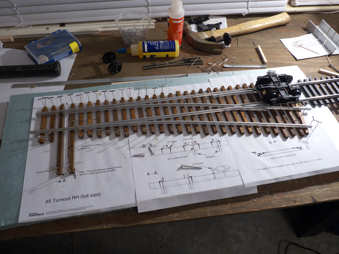
Building a turnout. Something different.

Thanks to a post on the largescalecentral forum by Bob Hyman, I found this site: handlaidtrack.com

You can download scale pdfs of various turnouts, crossings and other track stuff. By sizing that up by 280%, you get G scale turnout plans! Very cool.

Here is how I have gotten it to work. First, you need to download a free drawing program called InkScape. You can find it HERE

You will also need another program to chop up the finished file into letter page sized printable ‘parts’. It’s called ‘posterrazor’ and you can get it HERE.

Once you have these installed, open inkscape and choose ‘import’ from the file menu. Find your pdf (that you downloaded from handlaidtrack.com) and select that to import. Takes a bit, InkScape isn’t a speed demon.

Once it’s imported, go to Object->Transform. It should look like this:

inkscape

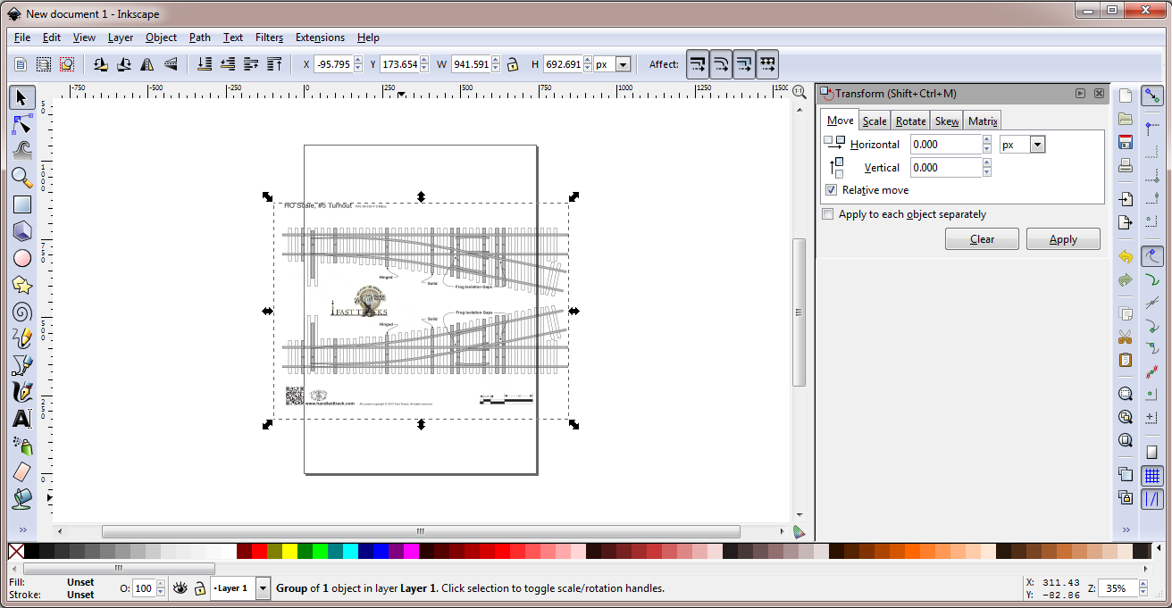
Click on the ‘scale’ tab at the top of the window to the right and then click ‘scale proportionally’. Change the width and height to 280 percent (It should be 300 strictly speaking but I’ve found that’s off just a bit so I use 280 instead). Click ‘Apply’ and the image will be resized. At this point, click the little selection on the right that has a percent in it (%) and change it to px so you know the dimensions of the image.

Now go to the file menu again and this time choose ‘export bitmap’. In the ‘Bitmap size’ area, enter the sizes from the step above. Choose an appropriate destination and file name and click ‘export’. I always use the ‘png’ format although I assume bmp would work as well.

Now open up the other program ‘posterrazor’. Load the png you exported in the above step into posterrazor. It should look like this:

pr

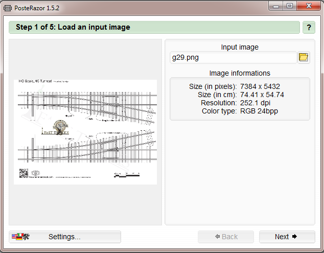
Click next and select ‘letter’ for the paper size and ‘landscape’ for the orientation. Click ‘next’ and just take the defaults presented there. Click ‘next’ again and select ‘size in percent’ and make sure that is set to 100% This should show you an image of how the large image will be broken up into several (many!) sheets of standard printer paper. Click next again and then click the little button under ‘save the poster’ This will create a new PDF sectioned off into the pages you need to print and then tape together to get a complete, full sized plan.

Note that for some of the pdfs on the handlaidtrack site, they are broken up into sheets already. You will have to load each of these sheets into inkscape and process each one like this to get a complete plan.

Also, I just print ONE page to test to make sure that the guage is correct before I print out the whole thing.

hhd-A
hhd-B

Here is my latest stand-alone hand-held-throttle design. It’s based on my control widget thing and I (finally) have it all working.

All the circuits and keyboard are mounted on a 3D printed faceplate with a 3D printed back enclosure. It still needs some structural work, screws to hold the face plate on and I need to mount the power switch too, not sure where that should go.

There is some hard-coded stuff in the handheld software but it does work quite well. I also have a slight design gotcha on my USB interface into this thing but I’ll get that solved soon.

pir-widget

I’m really enjoying my widget PCB design. Simple, cheap, easy bake oven for SOIC, program in C, add an Xbee for wireless real-time control, how cool is that? Here I have one hooked up to a parallax IR motion sensor. With a bit of C code it controls the servo based on the input from the motion sensor. Think railroad crossing signals- that crossing arm that comes dowm and blocks the traffic, right?

Anyhow, great fun and a good project to post over to controlwidgets.com

I’m looking at a $9 retail for board and components. Software will be free and open source. Of course 🙂

proto-frontproto-back

Getting a bit more physical here, I finally got a nice 3D print of the faceplate that works, this is number three I think. Mechanical design is much more difficult than I thought. Even with a 3D printer, some things just don’t go together like you think they should.

But so far, with some minor tweaks, it all fits.