Slow uptake

dash9

Not much new, I have gotten the Xbees to communicate in API mode. The only subsystem left to develop is the servo driver. Turns out I’m going to have to roll my own incarnation using timer 1. But that’s actually good, I don’t like depending on ‘libraries’ from third parties which often have deep dependency lists.

I’m also doing another pass on the RaspberryPi/Wixel/HTML5/Websockets project with the idea of releasing it open source or at least a collection of source code that mostly works. I hope to include the Master/Slave Wixel protocol thing I’ve had laying around for a while too.

Some very sad news too, Aristocraft Trains, who make one of the locomotives I really really want (pic above), is going out of business. Perhaps I can pick up a NS Dash9 before they go completely extinct but damn, that messes up some of my plans. Oh well. Shit happens.

xbeeProd

Have everything in terms of h/w working now. Just getting started on the UART drivers and then the formatting methods to build xbee frames. I’m going for the super simple series one point to point protocol. Technically this is not a ‘mesh’ network but for my purposes, it should do fine. The idea is to have any node talk to any other node directly. I don’t really need any sort of node hopping or self healing right now so I’ll opt for the simple first.

The handheld will function just like a standard R/C transmitter, moving servos and the motor controller in the locomotive. It will also be able to set various switches and relays and trigger sounds.

The big difference here between regular R/C and this- with this method I can do bi-directional data flows. So I can pick up position, speed and current consumption from the locomotive as well as send it commands. Also, since each device is a just another node on the network, an Xbee connected to my Raspberry Pi server will allow me to both control the locomotive and monitor it, the same as from the handheld.

In theory of course. However it is looking good so far. My h/w designs have proved both minimalistic and functional, so far anyhow, so I have a good feeling about getting all this working. The last stage will be the html5 tablet interface I did for the wixel, but that’s way down the road.

I’ve gotten both the client and master widgets working in terms of downloading and testing code. The display on the throttle is working great, the keyboard, not so much. Spent half a day before I realized I had wired the switch matrix sideways. Software comes up short when the h/w is hooked up wrong, eh?

The client node is simple, not much there other than the xbee interface via a dedicated serial link.

I have one more set of parts for the computer node, have not put them together yet. Really don’t need them that much now that I think about it, the Parallax xbee usb board I have should do it- but not sure yet.

9-12-2013: Have not had much time to finish up the keyboard but hopefully that will be done by the weekend. Other household repairs and refurbishments are taking up my time but they need to be finished up over the next few months as we move toward the cooler weather.

newradio

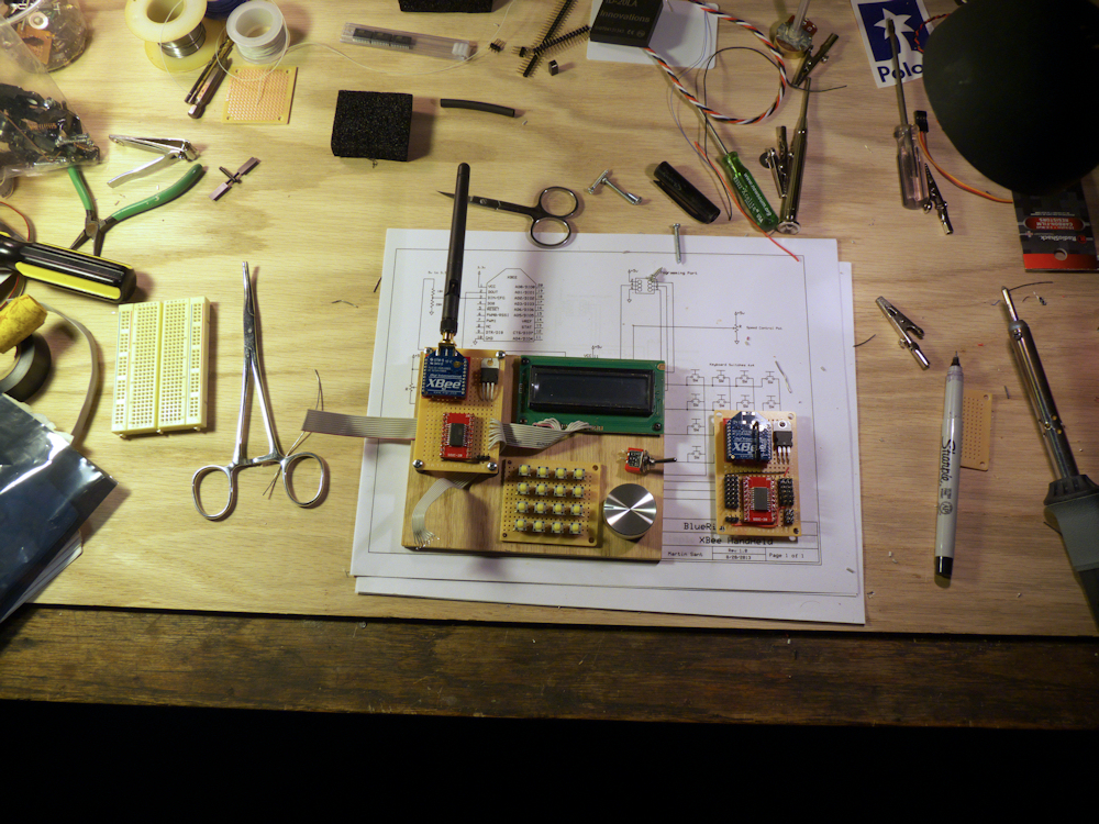
Spent most of the Holiday weekend finishing up the soldering on my various train widgets.

On the left is the Pololu 18v7 7 amp DC motor controller. This is a commercial board. It works great in my Aristo RS3 and allows bi-directional control without a reversing switch. It’s very configurable. You can run it bi-directional or single direction and it has configuration items for acceleration and braking although I have not tried those yet.

To the right of that is my ‘helper r/c’ design. This board reads r/c channels and converts the servo pulses to flip a relay (for reverse) and turn on up to three MOSFETs (for lights) using standard R/C airplane sorts of radios (one channel per). I noticed some people who use cheaper airplane ESCs are dedicating a servo to flipping a toggle switch onboard the locomotive, this eliminates that. (Personally, I like having a reverse switch so I configure my Pololu that way anyhow). This is a very inexpensive board based on the ATTiny84 micro-controller.

Not shown is an R/C sound board, it allows you to play any mp3 sound, triggered by a channel on the radio. Stick all the way to the left, play sound 1, all the way to the right, trigger sound 2, in the middle, silence. So horns, bells, or music even if you are so inclined. I’m thinking 1-4 channels of sound depending but I have not finalized that yet.

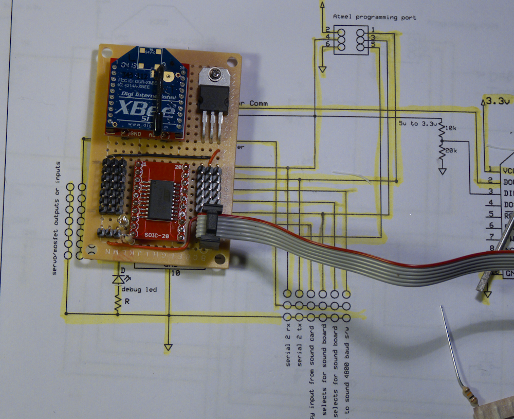
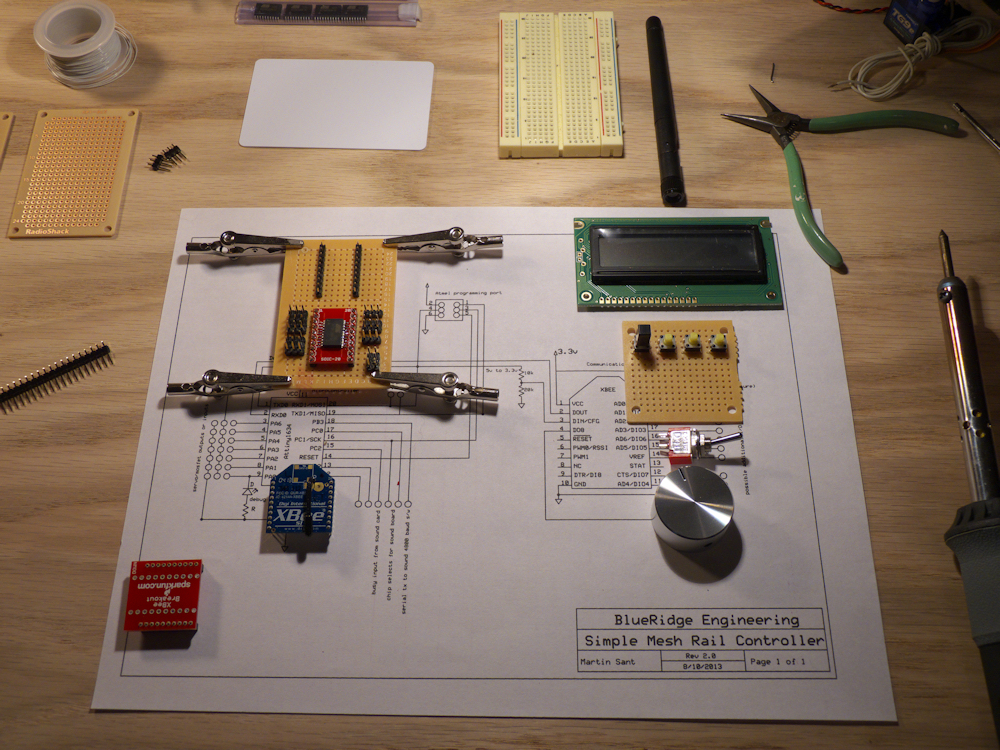
Next on the left, below the motor controller is my Xbee widget. This is going to be the basis of all of my new wireless designs. I can re-use the basice design and populate the board with different s/w only, no need to change the h/w to have several different ‘widgets’.

Depending on the s/w, I’ll be able to control servos, DC motor controllers, MOSFETS (on/off power switches) and drive my 4 channel mp3 sound card. I’d also like to provide the option of DCC outputs to feed various decoders but that s/w hasn’t been developed yet.

It will also provide serial inputs for things like RFID readers, speed and distance counters, current sensors and other things like that. Note that this doesn’t have to be a locomotive unit, this node could go anywhere to control turnouts or animatronics, etc.

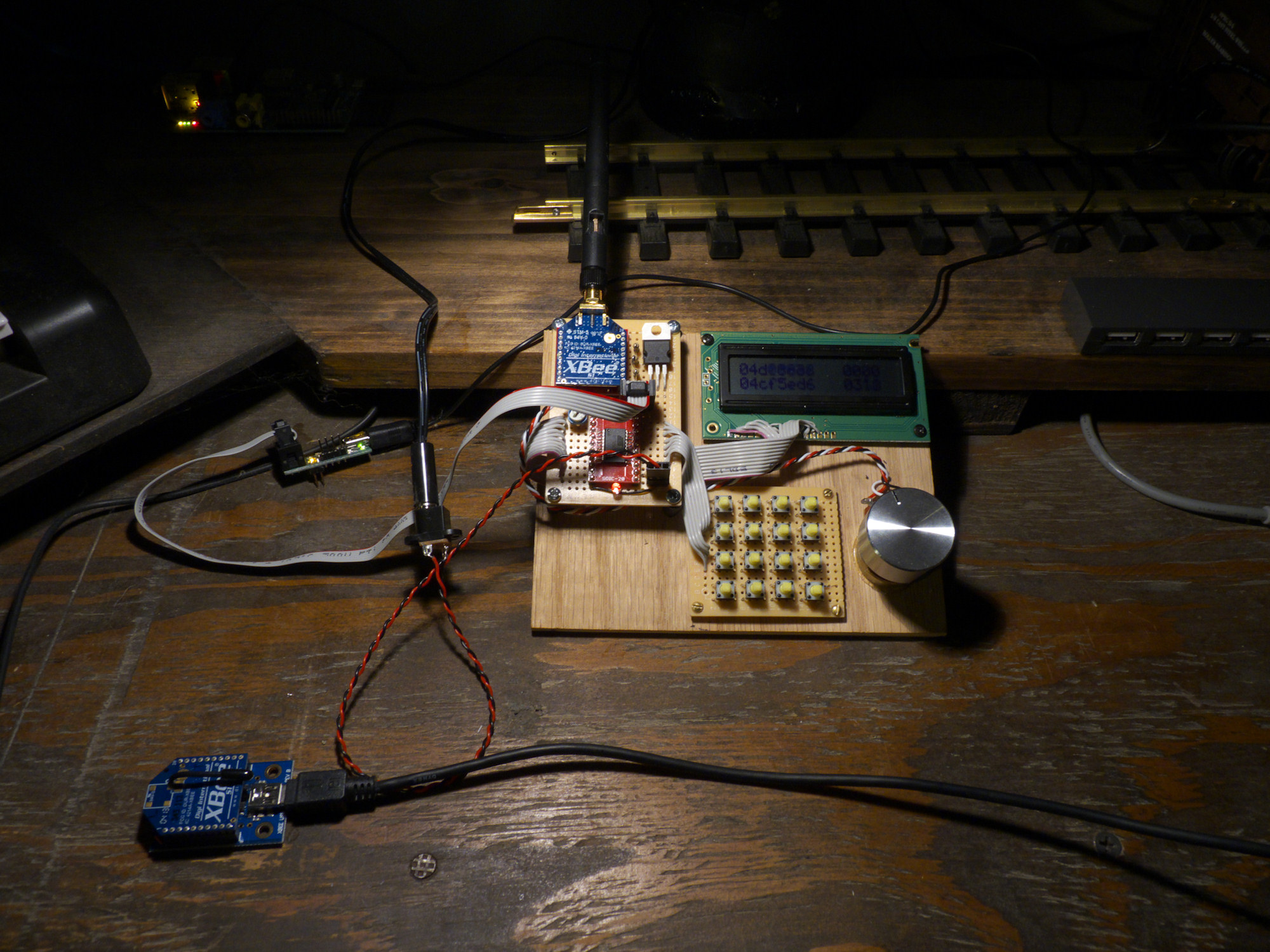
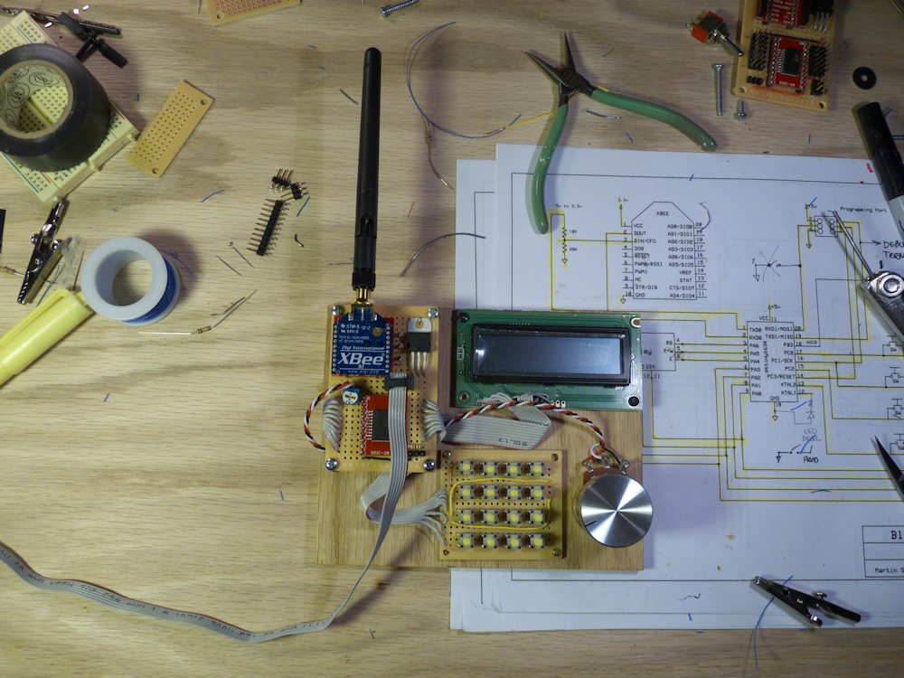
With another set of firmware, it will act as a hand-held controller. A rather large prototype of that is in the center of the picture. (This should fit down into a nice sized handheld unit once it’s put on a PCB)

Yet another incarnation of s/w will produce a widget that will interface to your computer, allowing control of any other widget.

The radio for the wireless is the Xbee series 1. These are low cost radio nodes, come ALREADY FCC certified and have a range of 300ft. They also provide a set of firmware called digimesh that turns your network of nodes into a self-healing mesh network. VERY COOL. The proctocol is also open source so no more proprietary radio communications! Love that.

zigbee

This is the client node. Three servo outputs, five mosfet outputs, serial out for sound card (up to 4 channels), serial in for RFID reader. Two inputs left over for speed sensor and/or current sensor. If I can come up with the proper code, I can drive DCC out of one of the Mosfets. There is some open source DCC code floating around but I wasn’t impressed with what I saw so that will probably have to be developed from scratch if I decide to.

bread1

Finished all the connections and parts placements. I dumped the toggle switch, why bother, just assign a button press to reverse the motor controller, right? I’m over thinking things again.

This is one of the more intricate breadboards I’ve done in a while. Continuity test tomorrow then a first software load. If the LED blinks, I’m golden 🙂

masterslave

More work on my prototypes. I have most of the boiler plate soldering done on the breadboards, the ground and power is all done for both. Signal paths are not, I plan to wire-wrap those. For the hand-held, I have a reasonable parts layout so that I can actually use this thing. I’m going to have to lay all this out on a PCB before I can design the actual hand-held enclosure but for now this will let me do all my development.

The ‘slave’ node on the right is super simple. Xbee and a micro-controller. All the work will be in the code. I’m planning 3 servo outputs, 5 mosfet digital outputs, a serial out for a two/four channel sound card and a serial input for the RFID transponder. If I can get the DCC protocol figured out and coded I’m going to put that in there as well. All this will leave one pin free for a possible distance/speed sensor. Anyhow, it should be a good development platform.

I guess it’s a bit of a misnomer to call these Master and Slave. While I’m going to start off with that, the idea is to eventually flash the Xbee modules with the digimesh firmware. This will make these just two equal nodes on the network. In this case, a hand-held control unit node and a locomotive (or whatever) node. Not shown yet (because I haven’t started on it, duh) is the computer node that will plug into my Raspberry Pi and offer sensing and control over the whole net. Or that’s the plan…

zibee1

Work begins on the new prototypes. Client to the left, basic layout of the hand-held to the right. The toggle switch is to reverse the locomotive, I’m not sure if it should be above or below the keyboard. Have to think on that one.

Closer shot of the client and the RFID transponder.

breadboard1