I’ve been playing around trying to get comfortable doing things with 2D vector drawings so that I can cut things out with my new 3D router. I think I’ve gotten the cut out a flat part operation and tool chain figured out, so I figured I would try to get a flat drawing into Blender and extrude it into a nice 3D part. Or I guess a 2.5D part? Anyhow, I wrote up a quick tutorial on it, here it is if you are interested. Click on any of the pictures for a full size image.
Convert 2D to 3D for free
First, you will need a couple of programs, Inkscape, a vector drawing program and Blender, a 3D program.
You can find Inkscape here:
https://inkscape.org/en/
And blender can be found here:
http://www.blender.org/
I don’t have a lot of experience with 2D programs so in order to get better at designing things for my 3D router to cut out, I’ve been playing with Inkscape.
Blender is a 3D program that I’ve actually used quite a bit so I decided to give it a try to make 3D objects out of flat vector drawings.
Draw a vector shape
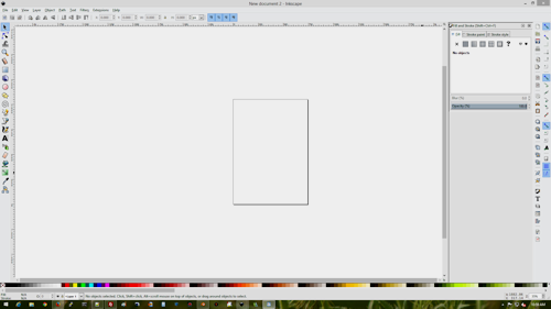
Inkscape is a very capable program but not too bad in the learning curve department. Open it up and the expand the window so it fits your whole screen.
The square in the middle is a 8×11 document. You can set this to any size you wish, but for now we can just leave it as so.
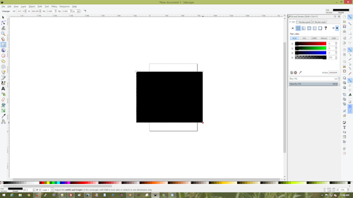
From the menu on the left, select the square tool. It’s just below the ruler and use it to draw a square on the screen. It should look like this:
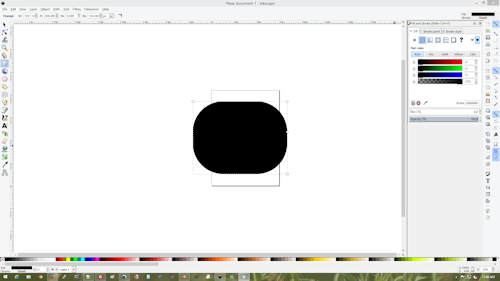
Notice the corners of the square, there are two round selectors, just for fun, grab the one in the upper right with the mouse cursor and drag it down. It will round the corners of the square.
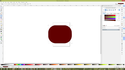
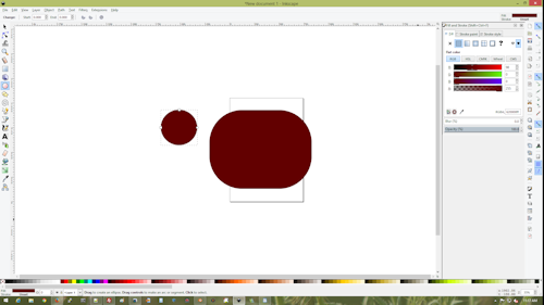
Again, just for fun, lets change the color of this shape. If it’s not already open, go to Object>Fill and Stroke. You should see a small window on the side of the screen. You can set the sliders to pick another color for your object. I’ve change it to a redish sort of color in this next pic.
Now lets draw some circles in the shape, we will turn these into holes in the next section after we have turned this into a 3D shape. Select the circle tool from the menu and draw a nice little circle next to your first shape. The size is not critical at this point.
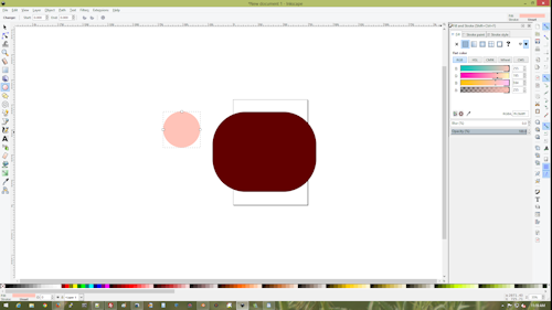
Use the same technique to change the color of the circle with the Fill and Stroke window. any color will do, it just needs to be different than the main shape.
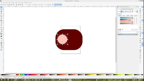
Now, select the arrow tool, it’s at the top of the left menu, and select the circle. Drag it onto the main shape and position it at one end.
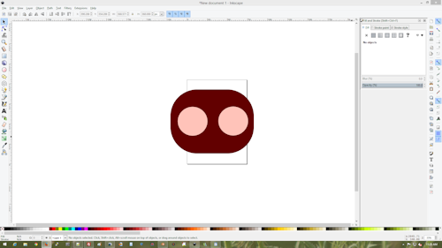
While the circle is selected, under the top meny, select Edit>Copy, then Edit>Paste in Place. it will look like nothing happened but it pasted another copyn of the circle directly over the original. Drag the circle over to the other side of the main shape. Note that you can make small adjustments to the position of the circle with the arrow keys too.
So now we are done with this flat vector image, it should look like the image above. Save it as a normal (the default) svg file.
2D to 3D
Ok, now open up blender. This is a really nice 3D program that can do almost anything. But of course, with that power comes a fair amount of learning curve and complexity. I’m just going to do something simple here, convert my flat vector to a 3D object so I’m not going to go into any of the complexities of the program. If you are interested there are literally tons of tutorials including many youtube videos on how to do all sorts of things with Blender.
When you first load blender you will see the spash screen, click at the top of that and it will go away. You should see a single 3D cube in the center of the screen, press the delete key and a small popup will appear asking if it’s ok to delete the cube, click delete.
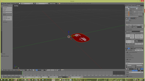
Now go to file>import and select Scaleable Vector Graphics (svg) this should be what you saved the above object created in Inkscape as. Find the object and import it. It will probably come in quite small depending on the size it was saved as in Inkscape.
To resize it larger in Blender, press the ‘B’ key and use the right mouse button to draw a box around the entire object. Once this is done, in the upper left corner menu, you should see a button labeled ‘scale’. Click this and then move the mouse to size the object larger or smaller. Click again to release the model.
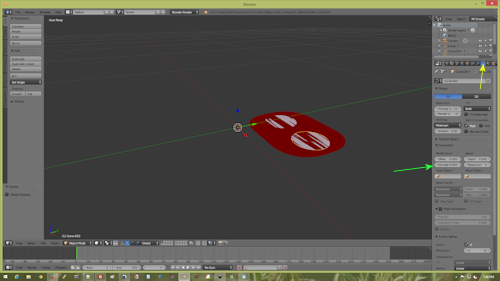
Now what we want to do here is select each part of the object and extrude it so it takes on a 3D shape. Right click on one of the circles in the object, it should get an orange ring around it to indicate it’s selected. On the complicated panel to the right, press the tiny button indicated by the yellow arrow in the next pic.
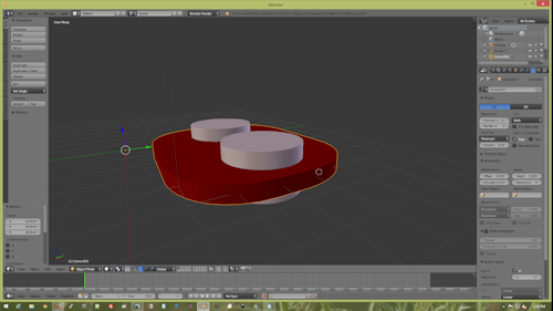
After you click that button, In that same image, note the ‘extrude’ parameter pointed to with the green arrow. At this point one of the circles should still be selected as indicated by the orange ring highlight. While it’s selected, click in the extrude box and type in a small number, say 0.03. You should see the circle change into a cylinder. Now select the other circle and do the same. Finally, select the main part of the object and type in a slightly smaller number for that one so that we can see the cylinders sticking out like in the following pic:
The idea here is that we are going to use a Boolean operation so the cylinders ‘cut’ holes in the main object part, then we will throw away the cylinders. But first, we have to convert this part into a 3D mesh part so we can do that.
Do this by selecting each of the parts again, the two cylinders and the main part using the right mouse button. Do this one at a time. Select the part, then in the menu at the bottom left, under ‘Object’, select the top option ‘Convert to’. You should see two selections in the pop up, choose ‘Mesh from Curve…’ Do the same for both the cylinders.
Now we want to export the part into a mesh format file. I like to use .obj files, others may work as well but I’ll stick with that one. Under File>Export, choose Wavefront .obj and give it a respectable name. I called mine ‘thing’.
Once it’s exported, go to the File menu and select ‘New’ to clear out this one. Delete the cube again and you should have a clean space to work in. Import the object you just exported File>Import and it should show up in the window. I will look exactly the same. However it is now a mesh object instead of a vector object.
What we want to do now is select the main part and then apply two boolean modifiers to it that will interact with the cylinders to ‘cut’ two nice neat holes in the main part.
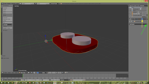
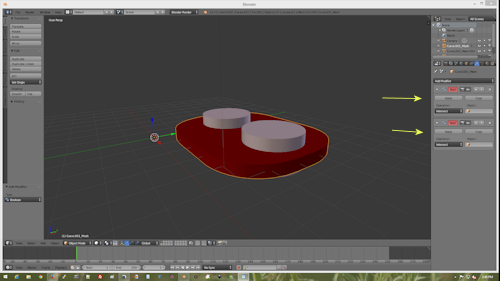
Click the button that looks like a wrench in the right menu, the one with the yellow arrow. You should see the ‘Add modifier’ button, the one pointed to by the green arrow. Make sure you have selected the main object (right mouse click on it) and then on the ‘add modifiers’ button, click it. You should see a whole bunch of options, in the second column from the left, there should be a ‘boolean’ selection, click it. Notice that it will add a modifier window under the Add modifier button. Now, do the same thing again so you have two modifiers.
Notice the ‘Object’ button on each modifier. This is where we tell it which of the two cylinders to use. Click in these and select one of the objects. There should only be two, each is one of the cylinders. In the ‘operation’ button, choose ‘difference’. Do this for both modifiers. Once selected, click ‘Apply’ on each of the modifiers. They will go away when you click the apply.
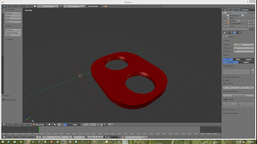
Now use the right mouse button to select the cylinders and hit the delete key for each in turn. You should now have a part with two nice neat holes.
This of course is only a demo and the part is not really worth anything but it does show some basic steps for getting a vector to a 3D model. I’m sure there are other ways and this may not be the best way to do things but it does work so there ya go 🙂
