Mr Rooster and some of his flock.
Mr Rooster and some of his flock.
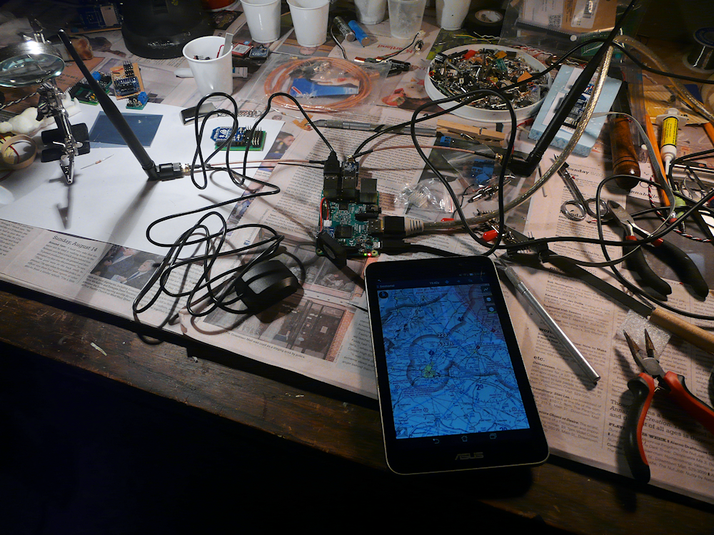
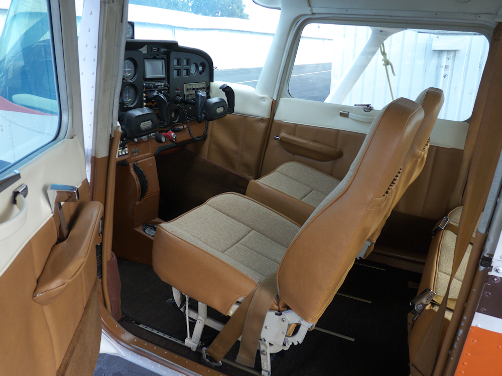
Something different, a gadget for the airplane. This is my incarnation of the Stratux open source ADS-B unit. It uses a Raspberry Pi3 along with a couple of high gain antennas, two radio receivers and a GPS unit to snatch weather and traffic data out of the air. For free! Can’t beat that. I think I spent a little over $100 on it, but I already had the Raspberry Pi3.
I also have an AHRS module plugged into it which should give me a basic Synthetic Vision system. Now I just have to figure out how to mount it ‘semi-permanent’ into the airplane. It has to be removable and used for ‘situational awareness only’ to be legal.
But one thing at a time. I’ve tried it with my two BLU phones and also my ASUS 7 inch tablet. So far so good. Works really well. Just plugged all the parts together, flashed the SD card with the free software and it comes up and runs. I’m trying out a couple of Android Apps that will work with it- they overlay the weather and traffic data on a current FAA sectional moving map plus let you do other cool stuff like plot out your file plan, get airport info and such. Neat.
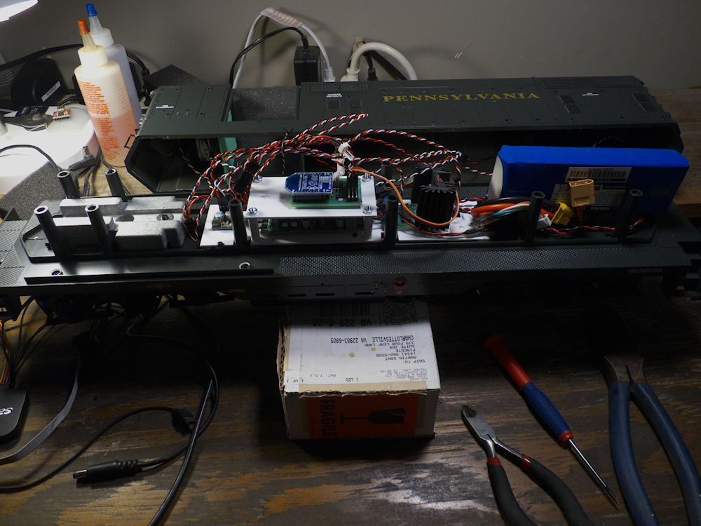
Got all the parts and pieces together (well almost) and did some testing outside on the layout. I was very impressed with the range, I have a new $50 BLU Studio phone and I’m getting a good 100ft. So far I have not seen any of the problems mentioned by other users of the TCS Wow 5amp. I did talk to tech support at TCS and they indicated that there had been some hardware changes to the 5amp since it was first released. He didn’t go into what they were and was not clear if the firmware changed or not. Mine is pretty new, I got it from RP about a month ago. He said there was no way to read the s/w version so I don’t know exactly what rev of firmware is in there. That is obviously on purpose for whatever reason.
But so far, I really like this decoder. Crisp sounds and I like the brake feature. Very cool that it ‘coasts’ when you shut down the throttle.
This is the first power on test of the decoder. I have not changed anything in the firmware or Android App from what I had with the Economi Decoder. I am using the 28/128 speed step which is the default in both decoders – so the extended packet format of DCC. The throttle, Bell and Horn all work out of the box, no configuration was done to the decoder before I tried this.
Because the TCS has some additional features and requirements, I will probably have to change the firmware and app side a little from the Economi implementation. It also has some sort of ‘mode’ to switch between the lights and sound functions so I will have to figure that out. That is the nice thing about a custom app, I can tailor it to each decoder.
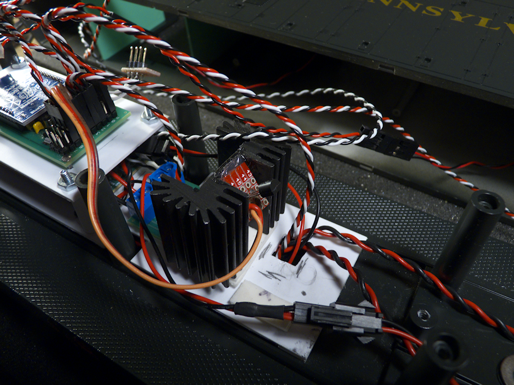
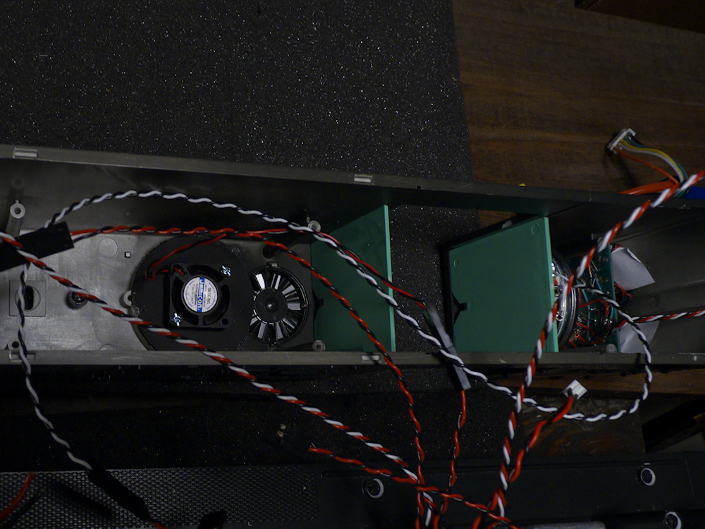
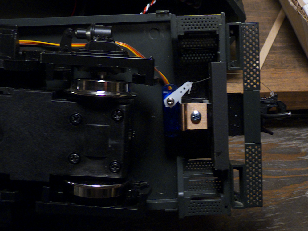
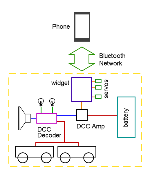
I also will be controlling a few extra things with this particular installation – I’ve got a temperature sensor mounted on the heatsink of the DCC amp. I also had a current sensor in there but it proved to be defective so I had to remove it for now. I’ve got two fans wired to function outputs on the decoder so I can turn those on and off. Two servos will be used to control the couplers as well. These will be implemented in the widget layer, they won’t be controlled by DCC so I can tailor that profile as well. Just yanking the couplers open doesn’t work very well, you need a smooth motion.
One other option will require a PCB mod. I want to be able to ‘name’ each BT module so it shows up in the phone as a locomotive number and description. The docs say I can use up to 20 characters for this. However it requires that you power up the device with a pin held low, then let it go high so it enters ‘AT’ mode. This will require either a special app or an extension to the one I have to set this plus a jumper on the PCB. I can work around this for now but I will add it to the PCB layout along with a couple of other spacing fixes for the next pass.


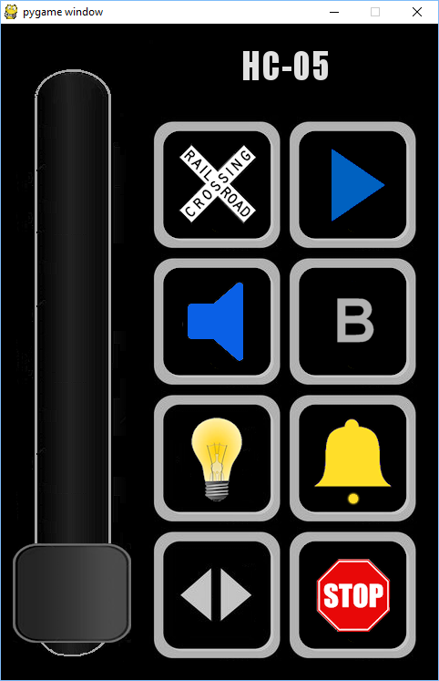
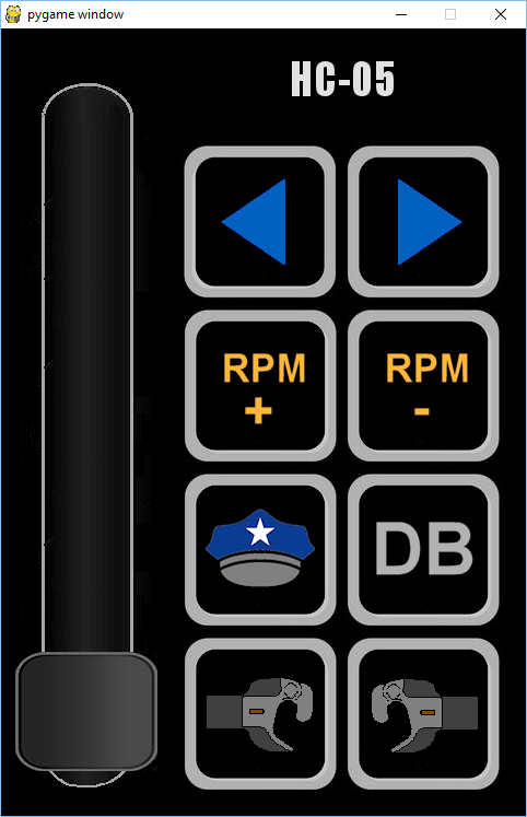


I think I’ve finally gotten to a beta release point on my Phone App and Widget Firmware. The firmware is universal but the phone app is customized for the Soundtraxx Economi DCC decoder. This app lets you control and program a battery powered locomotive via wireless DCC on your Android phone.. Above are the four screens. Some of the controls, the couplers in particular, are not implemented quite yet, or are implemented but untested. Everything else works. The coupler buttons are intended to control servos to actuate the couplers ala switching moves.
Below is a (rather long) video of the app driving the decoder on my little test setup. The blue readout is a current meter. Not pulling much here.
At some point I may try to merge the various incarnations of the phone app into one, but for now I’ll be doing one for each. I plan to support the three decoders I currently have, the QSI, the Economi and the TCS Wow.
Here is a demo of the phone app. It doesn’t actually do anything, just lets you change screens and move the throttle slider etc. But I’d be interested in feedback from other train folks – Drop me an email: martan@cstone.net
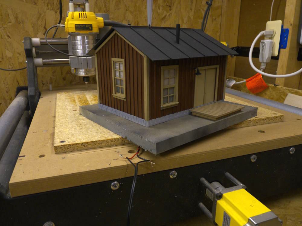
Newest building – the Proffit Yard Office. I’m building a new town just for this fellow.
Got my new boards in for the latest widget design. On the left is the DCC Amplifier, it turns the logic level signal from the widget into a 15v DCC signal. The board on the right is the new Megawidget.
I have moved away from SOIC components as they are hard as heck to solder by hand. So this one sports an Atmega328 28 pin thru-hole microcontroller. I still have one SOIC component, the 3.3v regulator for the network module but it’s a pretty easy hand solder and the thru-hole version is ridiculously large.
Another advantage to this microcontroller is I can run it at 16mhz using an external crystal. It’s a pretty speedy little sucker at that clock rate.
The boards came out perfect in terms of electrical connections, I didn’t have to cut any traces or add any jumper wires. However I do have a bit of a spacing problem on both the controller and the DCC amp that I will have to address on the next pass. The ISP programmer port is too close to the bluetooth module and the logic input on the AMP requires that I wire it instead of putting a pin header – but for now they are ok.
The plan is to refactor all of my existing code on the firmware side and get it all squeaky clean- bluetooth network, servo control and the DCC output. Hope to have that done this weekend. Eventually it will drive a TCS WOW Sound 5A DCC controller.
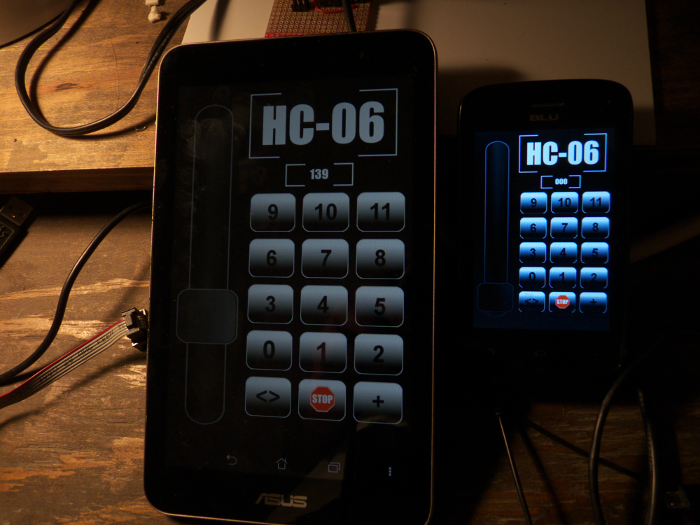
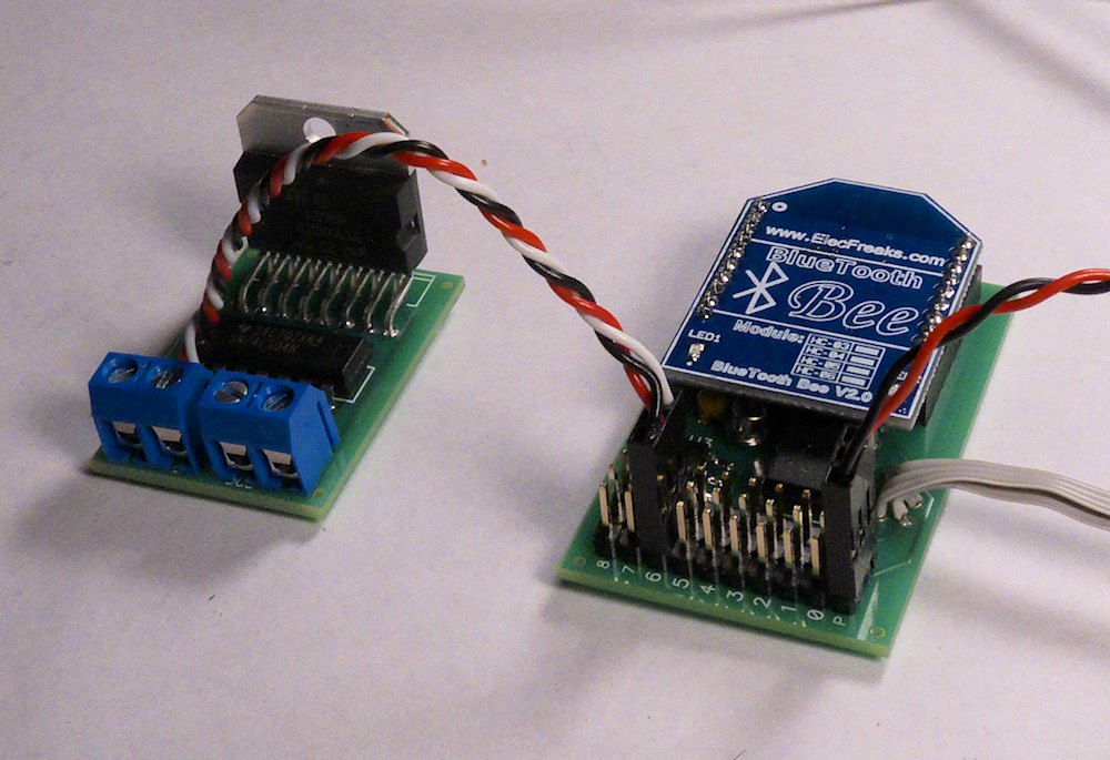
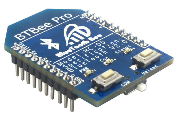
I pulled another project off the back burner and got the basics working. This is a Android Phone App I wrote in Python that interfaces to my control widget but with Bluetooth instead of 802.15.4. It uses the same DCC output code as all my other widgets but with a Bluetooth Network interface instead of Xbee. I seem to be late to the party all the time but I found this unit- it’s a pin Xbee compatible unit so it will fit right into my Control Widget design with no problems, just some different software. In the picture above, the unit on the left is my Asus 7″ tablet and the one on the right is a cheapo smart phone I got off of Amazon. Both work quite well. Not sure on the range yet, once I get the boards built I’ll be installing it all in my Aristo U25B for some real world testing.
I don’t have all the function codes working quite yet, but the throttle works great. This is all done with a BT board I’ve had laying around for a while- I have one of the above Xbee type units coming so I will be refactoring the code a bit for that anyhow. I should have boards for testing in about a week.
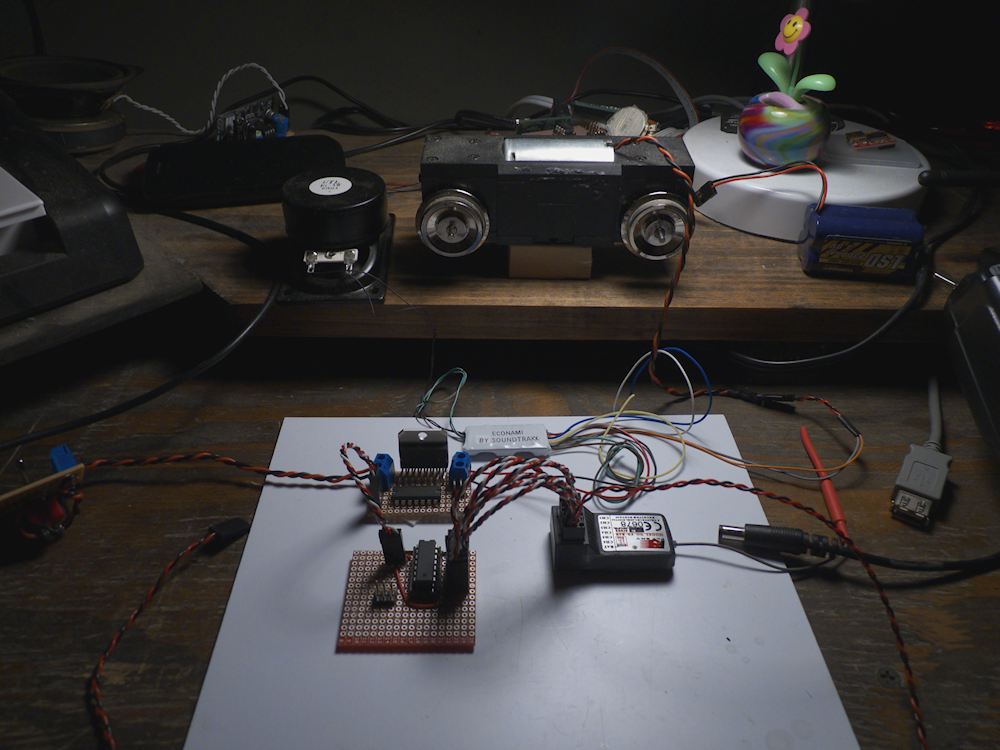
Here is an expansion of my R/C to DCC circuit. I now have all six channels of a cheap 2.4Ghz Radio Control System driving a 2Amp Economi DCC decoder. Throttle stick drives the speed, the other sticks trigger the bell, horn and other sounds. I have one of the switches doing the direction. The DCC amp can drive a 4A load with peak to 5A so more than enough for most G scale Here I’m driving a single USAT motor block. Still have a couple of small issues in the firmware but for the most part it works quite well. I am going to try to finish this off over the next few days and design a PCB for it.
Here is a diagram of the transmitter controls
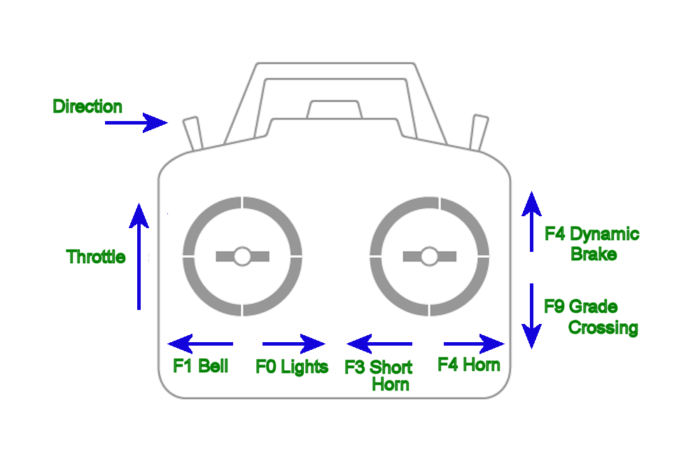
A video of everything working. Can’t quite see the blue LED that is the backup light, but the Headlamp LED is quite bright. I still have channel 5 open, not sure what to do with that one at the moment. Basically, you can do throttle, direction and 8 functions with a six channel system.