Other Stuff

masterslave

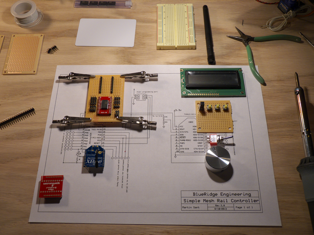
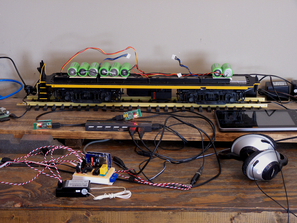
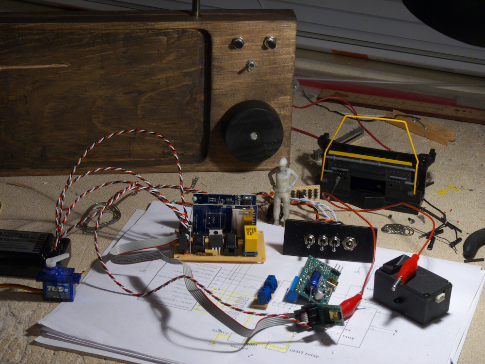
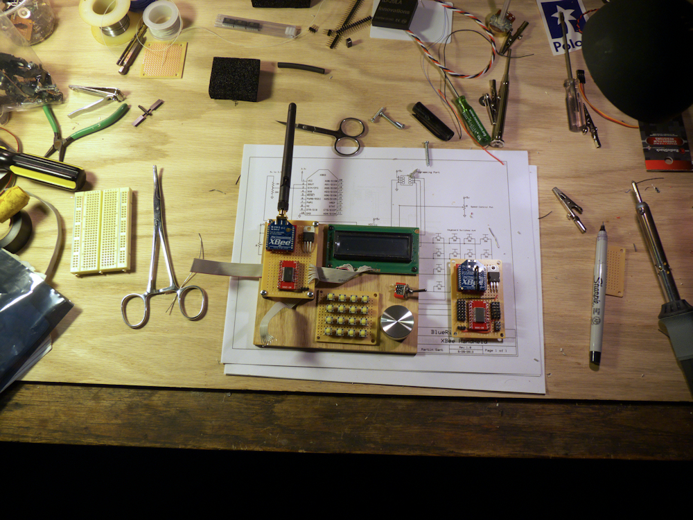
More work on my prototypes. I have most of the boiler plate soldering done on the breadboards, the ground and power is all done for both. Signal paths are not, I plan to wire-wrap those. For the hand-held, I have a reasonable parts layout so that I can actually use this thing. I’m going to have to lay all this out on a PCB before I can design the actual hand-held enclosure but for now this will let me do all my development.

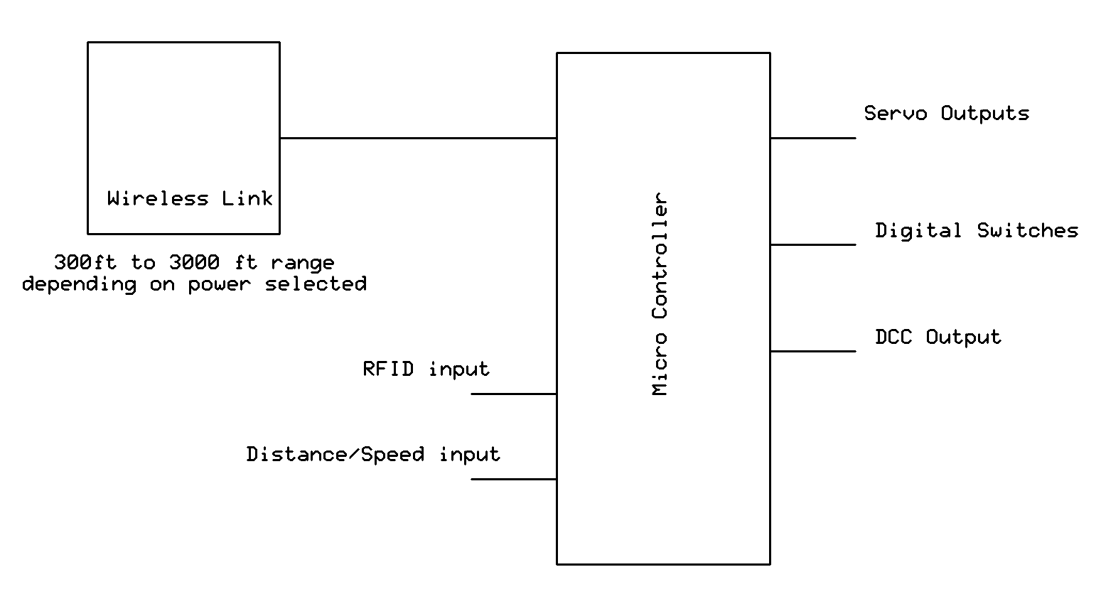
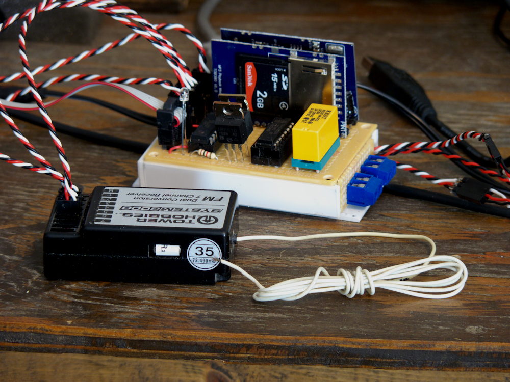
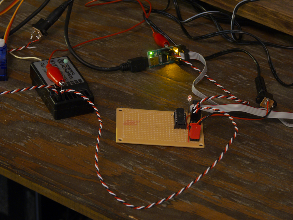
The ‘slave’ node on the right is super simple. Xbee and a micro-controller. All the work will be in the code. I’m planning 3 servo outputs, 5 mosfet digital outputs, a serial out for a two/four channel sound card and a serial input for the RFID transponder. If I can get the DCC protocol figured out and coded I’m going to put that in there as well. All this will leave one pin free for a possible distance/speed sensor. Anyhow, it should be a good development platform.

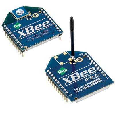
I guess it’s a bit of a misnomer to call these Master and Slave. While I’m going to start off with that, the idea is to eventually flash the Xbee modules with the digimesh firmware. This will make these just two equal nodes on the network. In this case, a hand-held control unit node and a locomotive (or whatever) node. Not shown yet (because I haven’t started on it, duh) is the computer node that will plug into my Raspberry Pi and offer sensing and control over the whole net. Or that’s the plan…

zibee1

Work begins on the new prototypes. Client to the left, basic layout of the hand-held to the right. The toggle switch is to reverse the locomotive, I’m not sure if it should be above or below the keyboard. Have to think on that one.

Closer shot of the client and the RFID transponder.

breadboard1

xdiagram

So this is the basic diagram for the locomotive (client node) side. I personally don’t need the DCC but I think that would be a good thing to have for compatibility if I can make it work. The motor controller is going to be external, I am assuming a Pololu 18v7 on servo channel 1. The wireless is the Xbee, you select the distance, the cheap one is 300 ft or so and the expensive one is up to a mile outside. The idea is to use an open source communications protocol in a very small, wireless mesh network environment and then provide a very low cost but expandable series of h/w boards to implement that. The end node can drive servos, digital outputs, dcc and provide real-time feedback like current draw, speed and position. That’s the plan anyhow.

xbee

Probably time to re-think the communications layer- master/slave with the Wixel works well but only has a 50ft or so range. Xbee is actually cheaper and offers a point to multipoint network out of the box. Duh. Also, if you want to spend the money, the PRO will do a freaking MILE in range! Sounds almost too good to be true, eh? We shall see.

So with that in mind, I’m also thinking of switching to the AVR 1634. It has two built-in usarts and extra i/o pins, however it is only available in a SMD package. Not terrible but a little more difficult to breadboard than a PDIP package.

Also found a nice free schematic drawing package from these guys:
ExpressPCB.com

But their PCB software kinda sucks (I like autorouting) so I’ll be sticking with these fellows:
Pad2Pad.com

P1030596

Battery Pack all finished and mounted. Plenty of room. I’ve decided to go ahead and wire up everything since I have the thing torn apart like this. I’ll be adding a Wixel that will be able to share control with the 2.4Ghz radio via a Pololu R/C multiplexor. I’m also planning on adding a set of Kadee Couplers controlled by a microservo. The final touch will be a Sparkfun ID-20 RFID reader which will interface with the onboard Wixel. By placing tags around the layout, this will let the locomotive know where he is in real-time.

P1030597

Sound card is working, now have sounds playing via radio control but I need to revise the clips and control algorithms. The amplifier/mixer is also still in the construction phase, these boards do drive a headset quite well, but don’t have the power to drive the speaker in the locomotive. Plus, just wiring the output of the two boards together works ok for debugging purposes but you get a drop in db when both are playing so that needs to be evened out. Nevertheless, the sound is quite good, I’ve been running it through my sound system here and it has the dog looking around for the train when I trigger the airhorns 🙂

rs3

I’ve been working on a home-made set of widgets to convert this locomotive to R/C and battery power. It’s a chance to do some circuit design, soldering and a bit of embedded software engineering for fun. The idea is to completely replace the insides of the locomotive with inexpensive, off the shelf components. I will use those to drive the main motive power- a 15v 3500mah Nimh battery array, and tap off that to provide stereo sound and lighting control.

While the motor controller was easy- I’m using the Pololu 18v7, the sound and R/C switches for the lights and the reversing power relay was where the fun was so I designed my own board. It uses an Atmel Attiny84 microprocessor, two mp3 player cards, a 3A power relay and two power mosfets.

Anyhow, the innards of the Aristocraft RS3 were not impressive. Complicated rats nest if you ask me. I have no interest in track power nor DCC so I just gutted the entire thing down to the leads on the motor trucks. I did save the two small circuit boards that plug into those but everything else with the exception of the 7805 power regulator got tossed.

rs3-gut

I have the sound/relay card almost finished, as things progress I’ll post more details. Here it is stripped all the way down:

stripped

And a picture of the motor truck, the colored wires are the motor leads, the two black wires go to the track pickups:

motortruck

Desktop Hacking

desktopS

Here is everything I’ve been playing with for the past few months in preparation for the RS3 battery conversion project. The hacked up R/C transmitter is in the back, note the pocket for my android tablet. The two buttons will be for sounds, the toggle switch is the reversing switch for the power relay.

The 3D print fellow is in front of that, I have a sitting version of him to replace the out of scale cartoon figure in the cab. The soundcard/relay/mosfet board is to the left and the pololu 18v7 motor controller is on the right in front of the switch harness. The power relay is wired and working off the intercepted servo signal of channel two.

The smoke generator is the black box at the far right, I think it needs its own hack. Sync’d to the motor control would be cool? I’m not sure about this one, not even sure it’s worth it to put it into the model at all. Obviously I need some testing on that first.

The Pololu USB AVR programmer/ttl serialport/sloscope widget is at the front with the red clip connected to the back. This is my ‘scope’ probe. An amazing board for the price! I tell you what, I am absolutely sold on the AVR series of chips and this programmer. The ATTiny84 does not have a serial port, yet I found a nice software uart for free at AVR freaks. I can hook one pin of the micro up to the serial input on the Pololu and that combined with an LED on one of the port pins gives me a decent set of debugging tools. Super cheap too, ATtiny84s are like $3 in singles, way less in qty.

Anyhow, the sound algorithms need to be fleshed out, the mounting of the boards is not right yet and I need to put together a solid battery pack. But I’m getting there 🙂

attinyS

I’ve been playing with the Atmel series of micro processor chips lately, specifically the ATtiny84 microprocessor. This is a 14 pin DIP chip that despite it’s size is actually quite powerful. You can download the free Atmel Studio 6 and use a low cost programmer like the Pololu AVR usb programmer ($20) and do C code. Quite a lot of fun.

I’ve managed to get a small code set working that uses nothing but the standard libraries included with Atmel Studio. It reads 6 channels of R/C from a generic airplane type radio control and breaks each channel down to an integer between 900 and 2000. I get a micro second resolution using the stock internal 8mhz clock, no external components at all! Very cool.

One thing that I thought was very handy- the Pololu USB AVR programmer has this nifty little application called SLOSCOPE. It turns two pins on the programmer into inputs for a light duty oscilloscope! Works great, I can see the R/C pulses and watch them change widths as I move the joysticks.

sloscope

motorcontrolS

Here is my motor controller design for my Alco RS3. I basically gutted the entire thing and rewired it using a Pololu 18V7 simple motor controller. I’ll combine that with a 2.4Ghz radio and my home brew sound card and it should be really cool. Not quite finished with it but it’s coming out quite nicely. I plan on wiring up a battery pack using C sized 3500mah NiMh batteries for motive power.

Actually, I think I’ve changed my mind on the wire harness a bit. I was going to use the Pololu Motor controller in the traditional way, ie, center joystick is off, all the way up is forward max, all the way back is reverse max. But after some contemplation, and getting the R/C decoder to work, I think I’m going to put a mosfet and DPDT power relay in play here. I’ll use one channel to flip the direction back and forth and then I can utilize the entire range of the joystick (a knob in the case of my hacked transmitter box) for applying power.